Download
1 / 72
900 likes | 1.44k Views
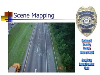
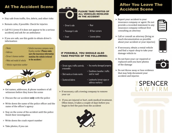
Basic Accident Scene Mapping. Patrick Riedlinger, P.E., ACTAR. What this lesson does. Shows you how to make a basic accident scene map Including identification of road scars Skid evidence Final rest positions. What this lesson does not do:. Teach you your “first response duties”

E N D
Basic Accident Scene Mapping Patrick Riedlinger, P.E., ACTAR
What this lesson does • Shows you how to make a basic accident scene map • Including identification of road scars • Skid evidence • Final rest positions
What this lesson does not do: • Teach you your “first response duties” • Teach how to secure the accident scene • Teach life, safety issues with the public • Make you an “Accident Investigator”
Topics • Effects of a collision • Tire marks • Road scars • Measuring/mapping • Equipment • Field examples
Objectives • After this lesson, you should be able to: • Identify different types of skid marks and how the types are created • Identify road scars and other roadway evidence • Identify and choose the best measurement method for field sketching • Produce a detailed field sketch
Effects of a collision • Tire marks • Road Scars • Debris
Tire marks • Skid mark • Yaw mark • Acceleration scuff • Flat tire mark • Imprint
Tire MarksSkids Note darker outside edges on upper picture- over deflection of tires Could be hard braking Could be under-inflation Could be overload Bottom picture shows locked wheel skid of all four tires Proper inflation Front tires are darker-as expected Striations parallel with the direction of travel
Tire Marks- Skid Upper picture- clearly locked wheel skid Middle Picture- Skip Skid Lightly loaded dual wheel truck Not a gap skid (release of brakes) Bottom- Example of Gap skid Driver releases brake, then re-applies
Yaw Marks-Example Yaw marks often curve and cross-over.
Tire Marks-Flat Tire Can go on for miles Shows under-deflection Dark edges Faint tire mark No Striations Usually only one flat tire Always tread width
Road Scars • Scratches and scrapes • Towing scratches • Gouges • Chips • Chops • Towing grooves • Fixed object scars • Debris
Road Scars-Scratches/Scrapes Made with little pressure Shows where metal parts slid across the road Towing away vehicle also can make scratches and scrapes
Road Scars-Gouges/Chips/Chops Made with heavy force Shows where strong metal parts dug into the road Examples: Frames, transmission housings, control arms. Chips are small, deep gouges Chops are long, narrow gouges like made by an axe
Road Scars-Towing Grooves Long narrow gouges Made by studs or lugs or drive shafts dragged along the road
Road Scars-Fixed Object Scars Off the road On trees, poles, guardrails, etc.
Debris • Dirt • Vehicle Parts • Cargo • Liquid • Personal Belongings
DebrisUnderbody Debris Includes mud, rust, snow, paint and gravel that was stuck to the underbody of the vehicle. Not an accurate way to determine first contact position If no skid marks, may be your only evidence
DebrisVehicle Parts Provides only some info on first contact position
DebrisLiquid Spatter Freckling occurs under high pressure Radiator rupture Fuel Motor Oil Dribbling occurs as vehicle moves from first contact to final rest position Puddling usually occurs at final rest position Very good for finding first contact position!
Measuring and mapping • Identifying points • Field sketching • Table of measurements
Measuring and Mapping:Identifying points • Accident reconstruction is dependent upon the evidence collected at scene • The ultimate goal is to documents enough evidence so that a scale diagram can be drawn from the measurements.
Measuring and Mapping:Identifying points • Before taking any measurements, decide on what data is to be sketched. • The final document will be two parts • A Field sketch • A table of measurements
Measuring and Mapping • Results of the collision-what to map: • Position of vehicles at final rest • Position of bodies • Gouges, chips, chops and grooves • Scratches and scrapes • Tire Marks • Roadside scars • Debris • Contact to fixed objects
Measuring and Mapping:Identifying points • First Task: How many points? • One point required for • A human body • Metal scars less than 3 ft in length • Contact to fixed objects less than 3 ft across • Spatter and puddles less than 3 ft across • Small debris areas less than 3 ft across • Dislodged vehicle parts
Measuring and Mapping:Identifying points • Two points are required for • Vehicles • Straight tire marks • Curved tire marks more than 3 ft, but less than 8 ft in length • Contact to fixed objects over long distances • Dribble paths
Measuring and Mapping:Identifying points • Three or more points are required for • Curved tire marks greater than 8 ft • Straight tire marks with angles, hooks, or gaps • Large debris areas
Measuring and Mapping:Identifying points • Assign letters to identify points • Use descriptive letters • “T” for truck, “C” for car • “G” for gouge, “D” for debris” • Use number suffix to identify multiple points for same object • D1, D2, D3, etc.
Measuring and Mapping Use multiple points for a “region” Number each point for consistency
Measuring and Mapping An example of mapping a wheel Must ALWAYS map two wheels Best if on same side of vehicle Attempt to pick undamaged wheels
Measuring and MappingField sketching • Coordinate Method • The coordinate method requires two measurements, or coordinates, to identify each point. • These measurements must be made from two permanent and easily identifiable landmarks.
Measuring and MappingField sketching • Coordinate Method-Reference Line • First, find a reference line (real or imaginary) that extends through the accident scene. • Usually denoted as “RL” in scene mapping • Reference Point • Establishes the origin (from which all the measurements are made) • Must be on the Reference Line, or can be “projected” to the line
Measuring and MappingField sketching • Coordinate Method-Directions • The direction of each measurement shall be specified • Compass directions of N, S, E and West are used • The measurements and directions form the coordinates of the point
Measuring and Mapping Example of coordinate mapping of an intersection
Measuring and Mapping Examples of reference lines for coordinate mapping
Measuring and MappingField sketching • Triangulation Method • The triangulation method requires two measurements, or coordinates, to identify each point. • These measurements must be made from two reference points (two RP’s, no RL’s) • A Triangle is formed between the two reference points and the point to be measured.
Measuring and MappingField sketching • Triangulation Method • Measure distance from on RP to the point • Forms one side of triangle • Measure distance from second RP to point • Forms second side of triangle • The distance between the RP’s forms the third side.
Measuring and Mapping Example of triangle mapping of an intersection
Measuring and MappingField sketching • Triangulation Method is useful when: • Roadways are irregular/indistinct. • Points are located more than 30 ft from reference line. • Points are located where no natural reference line exists.
Measuring and MappingField sketching • The Field Sketch • Should include the results of collision • Roadway features • Objects • Limit field sketch to factual data • Do not mark the “impact point”
Measuring and MappingField sketching • The Field Sketch • Should include a table of measurements • Is not to scale-is a freehand sketch • Identifies points of measurement by letters and numbers. • Indicates North somewhere on sketch
Measurement and Mapping Field Sketch Example
Measurement and Mapping Field Sketch Example
Measurement and Mapping Field Sketch Example