Download
1 / 28
290 likes | 480 Views
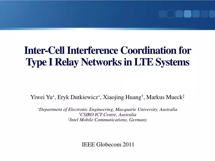
Inter-Cell Interference Coordination for Type I Relay Networks in LTE Systems. Yiwei Yu ∗ , Eryk Dutkiewicz ∗ , Xiaojing Huang † , Markus Mueck ‡ ∗ Department of Electronic Engineering, Macquarie University, Australia † CSIRO ICT Centre, Australia

E N D
Inter-Cell Interference Coordination for Type I Relay Networks in LTE Systems YiweiYu∗, ErykDutkiewicz∗, XiaojingHuang†, Markus Mueck‡ ∗Department of Electronic Engineering, Macquarie University, Australia †CSIRO ICT Centre, Australia ‡Intel Mobile Communications, Germany IEEE Globecom 2011
Outline • Introduction • System model • Problem formulation • Resource Allocation Scheme • Simulations • Conclusions
Introduction • LTE is an emerging wireless communication technology (4G) • Downlink:1Gbps • Uplink:500Mbps
Introduction • LTE is an emerging wireless communication technology (4G) • Downlink:1Gbps • Uplink:500Mbps • LTE vs. WiMAX
Introduction cell • Donor eNB (DeNB) eNB RN RN Donor cell UE UE UE UE UE UE • extend the coverage • increase the capacity of cell-edge users, who usually have weak links with the base station
Introduction TR36.814 • With respect to the knowledge in the UE, relays can be classified into • non-transparent, in which case the UE is aware of whether or not it is communicating with the network via the relay. • transparent, in which case the UE is not aware of whether or not it communicates with the network via the relay. • Donor eNB (DeNB) RN RN Donor cell UE UE transparent non-transparent
Introduction TR36.814 • Two types of relay node (RN) have been defined • Type I relay station:a relay may control cells of its own (non-transparent) • a unique physical-layer cell identity • relay can control RRM whose functionality are the same as eNodeB’s. • Type II relay station:a relay may be part of the donor cell (transparent) • the relay does not have a cell identity of its own (but may still have a relay ID) • Radio resource management (RRM) is controlled by the eNodeB to which the donor cell belongs
Introduction • Next generation wireless communications (4G) • high data rate • efficient resources (spectrum, power, etc.)usage • flexible network deployment • To meet these objectives, numerous new technologies and strategieshave been invented and developed (ex. OFDMA). • This paper combines OFDMA with relay techniques. In this complex environment, interference will become a serious issue.
Goals • In an OFDMA-based and relay-assisted network, develop • novel deployment of the relay architecture • dedicated SFR-based resource allocation scheme • effectively mitigate the interference • maximize the overall achieved throughput
System model • Type I relay networks • Frame structure • Transmission time interval (TTI) • Physical resource block (PRB) • one slot duration • 12subcarriers
System model • a seven-cell hexagonal system. • each cell has the same number of RSs with fixed positions. • one eNodeB is located at the center and six RSs are evenly distributed along the edges of each cell. • eNodeB is equipped with one omni-directional antenna. • RS is equipped with two 180-degree directional antennas to jointly serve the corresponding area of two adjacent cells. 6 5 1 0 2 4 3
System model • Cell-center users are only served by the eNodeB • Cell-edge users are served by RSs • Each cell-edge user is allowed to connect to only one RS, and served by this connected RS. • For simplicity, the decision on how cell-edge users select and connect to the RSs is only made on the distance. 6 5 1 0 2 4 3
Problem formulation • In above cellular relay network, we consider that each cell has MRSs and K users. • Kc cell-center users • Kecell-edge users ( ) • K = Kc+ Ke • The total transmit powers of an eNodeB and each RS are Pb and Pr . • The number of total PRBs that can be scheduled for downlink in each TTI is N. • Assuming that each PRB is assigned an equal power by the eNodeBor by RS • the transmit power for PRB n used by the eNodeBor RS can be denoted by pb = Pb/N and pr= Pr/N
Problem formulation • In each cell, the downlink communications are carried out in two steps in the time domain. • First, in time slot 1 • the transmissions from eNodeBto cell-center users • the transmissions from eNodeB to RS • Second, in time slot 2 • the transmissions from eNodeB to cell-center users • the transmissions from every RS to its connected cell-edge users
Problem formulation • The overall achievable capacity of a cell • the sum of the rates of the cell-center users connected to the eNodeB(Rc) and the rates of the cell-edge users connected through RSs (Re). • The rates of the cell-edge users are limited by the capacity bottleneck of the two-hop transmission • the minimum rates of the eNodeB-to-RS link and RS-to-cell-edge-user links.
Problem formulation • The objective of this paper is to optimize the capacity of a cell in each TTI. ABR:the rates of the eNodeB-to-RS link in the first time slot. ABU:the rates of the eNodeB-to-cell-center-user link in the first time slot. BBU:the rates of the eNodeB-to-cell-center-user linkin the second time slot. BRU:the rates of the RS-to-cell-edge-user link in the second time slot.
Problem formulation Wis the bandwidth of a PRB Γj,ndenote SINR for the corresponding transmission linkjon PRB n
Resource Allocation Scheme • In this paper, authors propose a two-step SFR-based resource allocation scheme • Step 1 Resource Allocation Method • in the first time slot transmission • Step 2 Resource Allocation Method • in the second time slot transmission
Step 1 Resource Allocation Method • Based on SFR, which is considered as the most effective frequency planning strategy • to mitigate inter-cell interference in LTE networks. • The basic idea of SFR • users are grouped as cell-edge and cell-center usersand the available spectrum is divided into two corresponding bands:a cell-edge band and a cell-center band. • Cell-edge users are restricted to the cell-edge band while cell-center users have exclusive access to the cell-center band and can also access the cell-edge band but with a lower priority.
Step 1 Resource Allocation Method • 1. Consider RSs in each cell as virtual cell-edge users in the first time slot. • 2. An SFR-like frequency reuse planning is applied on a seven-cell system transmission, including • the eNodeB-to-RS links and eNodeB-to-cell-center-user links the eNodeB-to-RS links only use a partial frequency band not overlapped with the adjacent cells while the eNodeB-to-cell-center-user links can use the entire frequency band including the reserved cell-center band as well as the cell-edge band only if it is available. 6 Higher transmitting power is given to the eNodeB-to-RS links compared to that of the eNodeB-to-cell-center-user links. 5 1 0 each RS can successfully receive signals from two eNodeBs of adjacent cells simultaneously through two different sub-bands in the first time slot transmission. 2 4 3
Step 1 Resource Allocation Method 6 5 1 0 2 4 3
Step 2 Resource Allocation Method • In the second time slot • eNodeB-to-cell-center-user links • RS-to-cell-edge-user links
Simulations • Average throughput of cell-center users in the reference cell as a function of edge users’ density
Simulations • Average throughput of cell-edge users in the reference cell as a function of edge users’ density.
Simulations • Average throughput of overall users in the reference cell as a function of edge users’ density.
Conclusions • This paper proposes a new relay network in LTE with resource allocation schemes • inter-cell interference coordination • performance improvement