Download
1 / 87
920 likes | 1.19k Views
Microprocessor and interfacing. 4 th Sem – Electrical . introduction. Microprocessor : It is a programmable logic device that can be used to control processor to turn on/off the device.

E N D
Microprocessor and interfacing 4th Sem – Electrical
introduction • Microprocessor : • It is a programmable logic device that can be used to control processor to turn on/off the device. • It is a programmable integrated device that has computing and decision making capability similar to that of CPU.
Conti… • The microprocessor communicates and operates in the binary numbers 0 and 1 , called bits. • Each microprocessor has a fixed instructions in binary patterns called machine language. • However it is difficult for human to communicate in the language 0s and 1s. Hence the binary instructions are given abbreviated names , called mnenomics , which form assembly language.
Conti… • Microprocessor is a set of instruction, designed internally to manipulate data and communicate with peripherals. • This process of manipulation and communication is achieved by the logic design of the microprocessor, called architecture.
Conti… • It consists of various functional block as listed below : • Interrupt control • Serial I/O control • Register Array • ALU • Instruction decoder and machine cycle • Timing and control circuit • Address/data buffer • Address latch (incremental / decremental)
Conti… • Interrupt : • They are external signals provided to microprocessor to stop its current execution. • Interrupt controller : • It is responsible to generate interrupt and receive acknowledgement about its interrupt.
Serial I/O control • It controller serial communication when data is being sent/ received. • It receives data on • SID • SOD
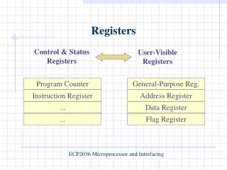
Register array • Accumulator • Temporary register • Flag registers • Instruction register • General purpose register • Stack point and program counter
Conti… • Accumulator : • It is an 8 – bit register which is used to store 8-bit data and to perform arithmetic and logical operations. • The results of these operations are stored in accumulator. • The accumulator is connected to ALU and it is also defined as Register A.
Conti… • Temporary register : • These registers are used for intermediate storage of any arithmetic and logical operation. • These registers are internally used ; they are not available to programmer • They are 8-bit register . (Temp Reg. W and Temp. Reg. Z)
Flag registers • It is an 8-bit register , in which five of the bits carry significant information in form of flags. • The flags are set or reset according to the result of arithmetic and logical operation. • hence the flags reflects the condition of data (result) which is stored in accumulator.
Conti… • They are called Zero(Z), Carry (CY), Sign (S), Parity (P), and Auxiliary Carry (AC) flags; The most commonly used flags are Zero, Carry, and Sign. • The microprocessor uses these flags to test data conditions.
Conti… • For example, after an addition of two numbers, if the sum in the accumulator id larger than eight bits, the flag uses to indicate a carry -- called the Carry flag (CY) – is set to one. • When an arithmetic operation results in zero, the result called the Zero(Z) flag is set to one. • The flags are stored in the 8-bit register so that the programmer can examine these flags (data conditions) by accessing the register through an instruction. • These flags have critical importance in the decision-making process of the microprocessor.
Instruction register • Instruction register will store the 8-bit instruction given by the programmer. • Further it is fed to instruction decoder and machine cycle encoder which decodes the instruction in machine language.
General purpose registers • B,C,D,E,H and H are 8-bit general purpose registers. • It could be used as separate 8-bit register or as 16-bit register pairs , BC, DE , and HL. • When used in register pair mode , the high order byte register in the first register and low order byte in the second. • HL pair also functions as a data pointer or memory pointer. These are also called scratchpad registers , as user can store data in them. To store and read data from these registers bus access is not required, in is an internal operation. • Thus it provider an effective way to store intermediate results and use them when required. • The efficient user prefers to use these registers to store intermediate results than the memory locations which require bus access and hence more time to perform the operation.
Program Counter (PC) • This 16-bit register deals with sequencing the execution of instructions. This register is a memory pointer. • Memory locations have 16-bit addresses, and that is why this is a 16-bit register. • The microprocessor uses this register to sequence the execution of the instructions. • The function of the program counter is to point to the memory address from which the next byte is to be fetched. When a byte (machine code) is being fetched, the program counter is incremented by one to point to the next memory location
Conti… • Stack Pointer (SP) • The stack pointer is also a 16-bit register used as a memory pointer. It points to a memory location in R/W memory, called the stack. • The beginning of the stack is defined by loading 16-bit address in the stack pointer. • The stack is a reserved area of the memory in the RAM where temporary information may be stored.
Instruction decoder and machine cycle encoder • When an instruction is fetched from memory , it is loaded in the instruction register. • The decoder decodes the instruction and establish the sequence of events to follow. • Each instruction take few time period, called machine cycle. This machine cycles are generated by machine cycle encoder.
Timing and control unit • This unit synchronizes all the microprocessor operations. • Timing signals are used to built & generate clock. • Control signal are used to initiate/ terminate any operation.
ALU (arithmetic and logic unit) • It performs arithmetic and logical functions on eight bit variables. • The arithmetic unit performs bitwise fundamental arithmetic operations. • it includes • Accumulator • Temp. Reg • Five flags • They performs arithmetic operation , logical operation as well as branching operation.
Conti… • Arithmetic operation : • Addition • Subtraction • Increment/ decrement • Logical operation: • AND , OR, EX-OR • Rotate : Each bit in accumulator can either rotate left or right • Compare • Complement : Any content of accumulator will be complemented. All 0s will be replace by 1s.
Conti… • Branching operation: This alters the sequence of program execution either conditionally or unconditionally. • Jump • Call , Return , restart
Conti… • The 8085 registers are classified as : • General purpose Registers • Temporary Registers • Temporary data register • W and Z registers • Special purpose registers • Accumulator • Flag registers • Instruction register • Sixteen bit registers • Program Counter (PC) • Stack pointer (SP)
8085 bus structure/ organization • The 8085 MPU performs memory read / write , I/O read / write functions using three sets of communication lines , called buses. • The address bus • The data bus • The control bus • These buses as a group is defined as system bus. • These buses are set of conductors/ transmission lines that connect the MPU to its memory and I/O devices.
main features • It is a 8 bit microprocessor. • It is manufactured with N-MOS technology. • It has 16-bit address bus and hence can address up to 216 = 65536 bytes (64KB) memory locations through A0-A15 . • The first 8 lines of address bus and 8 lines of data bus are multiplexed AD0 – AD7 . • Data bus is a group of 8 lines D0 – D7 . • It supports external interrupt request. • A 16 bit program counter (PC) • A 16 bit stack pointer (SP) • Six 8-bit general purpose register arranged in pairs: BC, DE, HL. • It requires a signal +5V power supply and operates at 3.2 MHZ single phase clock. • It is enclosed with 40 pins DIP (Dual in line package).
X1 &X2 (pin 1-2)( input) • These are also called Crystal Input Pins. • To generate clock signals internally, 8085 requires external inputs from X1 and X2.
Reset in (pin 36) • It is used to reset the microprocessor. • It is active low signal. • When the signal on this pin is low for at least 3 clocking cycles, it forces the microprocessor to reset itself.
Conti… • Resetting the microprocessor means: • Clearing the PC and IR. • Disabling all interrupts (except TRAP). • Disabling the SOD pin. • Gives HIGH output to RESET OUT pin.
Reset out (pin 3) • It is used to reset the peripheral devices and other ICs on the circuit. • It is an output signal. • It is an active high signal.
Conti… • The output on this pin goes high whenever RESET IN is given low signal. • The output remains high as long as RESET IN is kept low.
SID (pin 5) • SID : serial input data • It takes 1 bit input from serial port of 8085. • Stores the bit at the 8th position (MSB) of the Accumulator.
SOD (pin 4) • SOD : serial output data • It takes 1 bit from Accumulator to serial port of 8085. • Takes the bit from the 8th position (MSB) of the Accumulator.
Interrupt • It means interrupting the normal execution of the microprocessor. • When microprocessor receives interrupt signal, it discontinues whatever it was executing. • It starts executing new program indicated by the interrupt signal. • Interrupt signals are generated by external peripheral devices. • After execution of the new program, microprocessor goes back to the previous program.
Classification of Interrupts • Maskable and Non- Maskable • Vectored and Non-Vectored • Edge Triggered and Level Triggered • Priority Based Interrupts
Maskable interrupts • Maskable interrupts are those interrupts which can be enabled or disabled. • Enabling and Disabling is done by software instructions.
Non-Maskable Interrupts • The interrupts which are always in enabled mode are called nonmaskable interrupts. • These interrupts can never be disabled by any software instruction.
Vectored Interrupts • The interrupts which have fixed memory location for transfer of control from normal execution. • Each vectored interrupt points to the particular location in memory.