Download
1 / 16
200 likes | 462 Views
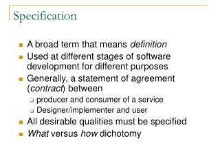
Chapter 2 Test Specification Process. Device Specification Sheet Purpose Design Specification Determine functionality of design Test List Generation Insure device lives up to spec sheet claims Communication Verify that device is appropriate for the end application Flexible Document

E N D
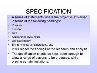
Device Specification Sheet • Purpose • Design Specification • Determine functionality of design • Test List Generation • Insure device lives up to spec sheet claims • Communication • Verify that device is appropriate for the end application • Flexible Document • Ownership - catalog or custom? • Allows changes to specifications • Avoid ambiguities • Late Changes in Specification Sheet Indicates Poor Organization
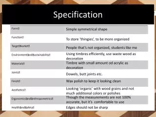
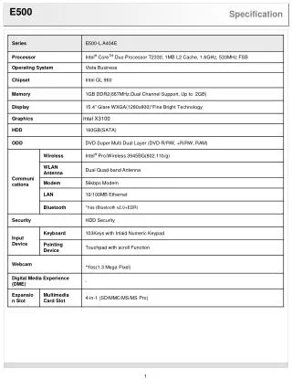
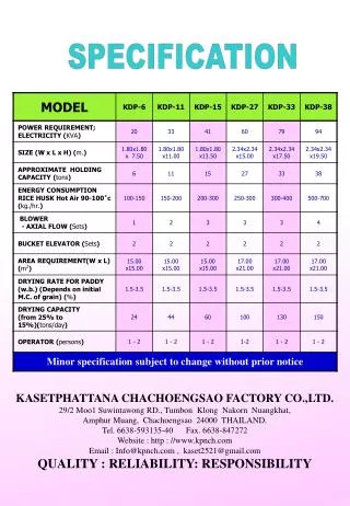
Device Specification Sheet • Structure • Feature Summary • Quick look at functionality of chip • Principles of Operation • Detailed device function • guaranteed by functional or parametric test program • Absolute Maximum Ratings • Failure limits of chip • not critical to a test engineer • Electrical Specifications • Core of parametric tests • Test conditions are listed as notes • MAX, MIN, TYP, guaranteed by design
Device Specification Sheet • Structure • Timing Diagrams • Critical to test program development • Manually generated for frequency synchronization • Application Information • Aids customer in designing end application • Functional block diagram • shows top level representation of device function • Characterization Data • Data collected during testing i.e. parameter histograms • Circuit Schematics / Die Layout • Device functional pin representation and layout
Generating the Test Plan • To Plan or Not to Plan? • Shoot From the Hip Approach • Non-optimized • May cause a device to be Non-testable • Planned Testing • Allows early interaction between design and test engineers • Identification of non-testable functions • Synchronization of clocking schemes • Tester hardware identification • identify tester hardware deficiencies
Generating the Test Plan • Purpose of a Test Plan • Less Formal than a Device Data Sheet • Test Engineers Roadmap to Generate Test Program • Official Communication Tool • Test engineer • Design engineer • Product engineer • Customer
Generating the Test Plan • Structure of a Test Plan • Device Background not Found in Data Sheet • Special Test Requirements • Explanation of the Purpose of Each Test • Assumptions regarding particular test and why • Hardware Setup Diagram for each Test • All Documentation should be Tester Independent • Tester Specific Information should be added as a separate section
Generating the Test Plan • Design Specifications vs. Production Test Specifications • Production Testing is very Time Critical!! • Not all Design Parameters need to be Tested in Production • Identification of Critical Test Parameters • Minimum Testing to Reduce Test Time while Insuring Device Functionality
Generating the Test Plan • Converting the Spec Sheet into a Test Plan • Infinite Permutations of Possible Tests Indicated by Data Sheet • Caution is necessary due to signal interactions • How does the Test Engineer know which Tests are needed in Production Testing?? • For each sentence in the device description, there should be at least one test that verifies the claim • Max. and Min. electrical specifications must all be verified • Worst case failure modes are often used to limit the number of tests required to verify the device function • Extensive testing of a device will reveal more tests which need to be added or can be omitted
Components of a Test Plan • Test Program Structure • Coded Version of the Test Plan • Waveform creation / Tester initializations • Calibrations • Continuity • DC parametric tests • AC parametric tests • Functional tests / Digital patterns • Digital timing tests • Test sequence control • Test limits • Binning control
Components of a Test Plan • Test Code and Digital Patterns • Test Code • Controls order and timing - does not create timing signal • instrument settings • signal generation • signal measurements • Digital Patterns • Consists of groups of data called vectors • drive data for each pin • expect data for each pin • Vectors are sent out at a regular rate “bit cell rate” • Tight frequency control is critical • Allow looping and branching of vectors
Components of a Test Plan • Binning • Grading of Devices into “Bins” • Performed by handler • Pass or Fail • Continuity Fail - could indicate handler error • Different grades of device based upon performance • 100 MHz chip vs 120 MHz chip • Fast Binning • Device is rejected as soon as it fail first test • Reduces test time
Components of a Test Plan • Test Sequence Control • Sequencers • C program coded • Graphical user interface controlled • Waveform Calculations and Other Initializations • Pre-computed Waveforms • Performed only once when the program is loaded • tl_init function in Teradyne architecture • Reset of tester Instrumentation to Default State • Focussed calibrations • Checkers
Components of a Test Plan • Focussed Calibrations • Tester does not have Sufficient Accuracy for a Test • Determines the Inaccuracy of a Fast Instrument using Slower, more Accurate Instrumentation • Software compensation allows a more accurate result. • Not absolutely perfect - still has the inaccuracy of the more accurate instrumentation • Software Calibration due to DIB Design • DIB Checkers • Checks for Faulty Op-Amps, Comparators, and Relays often placed on the DIB • Avoids running thousands of devices on a bad DIB board
Components of a Test Plan • Characterization Code • Used for Characterization of First Production Devices • Very Thorough Testing to Identify and Correct Marginal Portions of the Design • Simulation Code • Added to Test Program to Allow Mathematical Routines to be Verified • Offline Debugging of Test Code • Avoids wasting valuable tester time
Components of a Test Plan • Debuggability • Debugging Consumes 20% of a Test Engineers Week • Test code bugs • Hardware errors • Correlation errors • Intermittent failures • DIB errors • Broken tester modules • Design Debugging • Ability to modify code to isolate a device function • Run experiments for designers or customers to verify device