Download
1 / 16
160 likes | 291 Views
Chapter 5. Multiview Sketching & Projection. Print handouts Select File, Print Edit the following selections to read: Select the OK button. Orthographic Projection.

E N D
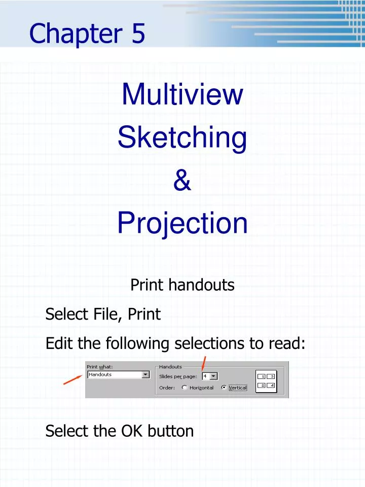
Chapter 5 Multiview Sketching & Projection Print handouts Select File, Print Edit the following selections to read: Select the OK button
Orthographic Projection • A system of drawing views of an object using perpendicular projectors from the object to a plane of projection (I.e. paper)
Six Standard Views • Top, front, right side, left side, back and bottom • Front • Usually shows most detail • If applicable – should show object in operating condition (I.e. car)
View Placement (3rd angle projection) • Front view usually shows the most detail Projection Lines • Why must views be arranged so that they align? • To make it possible for someone to interpret the drawing.
The Glass Box Metaphor • Imagine that the object you are going to draw is positioned inside a glass box, so that the large flat surfaces of the object are parallel to the walls of the box. • 2 horizontal planes • 2 frontal planes • 2 profile planes • From each pointon the object, imagine a ray, or projector perpendicular to the wall of the box forming the view of the object on that wall or projection plane. • 2 horizontal planes (top and bottom views) • 2 frontal planes (front and back views) • 2 profile planes (right and left side views)
Unfolding the Glass box • For Third Angle Projection (the method in the U.S.) • Imagine that the walls of the box are hinged and unfold the views outward around the front view. • This will give you the standard arrangement of views for 3rd Angle Projection which is used in the US, Canada, and some other countries.
Third Angle Projection: Symbol forthird angle projection shown on dwg Third angle projection Standard for USA, Canada and our class! First Angle Projection: First angle projection Primarily used in Europe and Asia! Symbol forfirst angle projection
DEMO • If a point, line or plane is in one view, it must be in all the views.
Precedence of Lines • When visible lines, hidden lines and center lines coincide remember: • Visible lines take precedence over hidden lines • Hidden lines take precedence over center lines, For example: Figure 5.32
Example • Do Hands-On 3 together • Need • HB pencil • Engineering Calculation Paper • Model • Instructions (Sept. Schedule of Assignments in Angel) • Follow instructions • Remember specs for the border & title block are included in the Penn State Erie Graphics Standards and in Handouts folder in Angel • Label • Views – TOP, FRONT, etc.
Hands-On 4 • Instructions on the web