Download

1 / 79
800 likes | 938 Views
Memory Hierarchy. Outline. Random-Access Memory (RAM) Nonvolatile Memory Disk Storage Locality Memory hierarchy Suggested Reading: 6.1, 6.2, 6.3. Nonvolatile: 非易失的. 6.1 Storage Technologies. 6.1.1 Random-Access Memory. Random-Access Memory (RAM). Key features

E N D
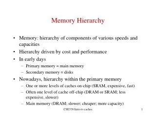
Outline • Random-Access Memory (RAM) • Nonvolatile Memory • Disk Storage • Locality • Memory hierarchy • Suggested Reading: 6.1, 6.2, 6.3 Nonvolatile: 非易失的
Random-Access Memory (RAM) • Key features • RAM is packaged as a chip. • Basic storage unit is a cell (one bit per cell). • Multiple RAM chips form a memory.
Random-Access Memory (RAM) • Static RAM (SRAM) • Each cell stores bit with a six-transistor circuit. • Retains value indefinitely, as long as it is kept powered. • Relatively insensitive to disturbances such as electrical noise. • Faster and more expensive than DRAM.
Random-Access Memory (RAM) • Dynamic RAM (DRAM) • Each cell stores bit with a capacitor and transistor. • Value must be refreshed every 10-100 ms. • Sensitive to disturbances. • Slower and cheaper than SRAM.
Tran. Access per bit time Persist? Sensitive? Cost Applications SRAM 6 1X Yes No 100x cache memories DRAM 1 10X No Yes 1X Main memories, frame buffers SRAM vs DRAM summary Figure 6.2 P458
16 x 8 DRAM chip cols 0 1 2 3 memory controller 0 2 bits / addr 1 rows 2 supercell (2,1) (to CPU) 3 8 bits / data internal row buffer Conventional DRAM organization • d x w DRAM: • dw total bits organized as d supercells of size w bits Figure 6.3 P459
16 x 8 DRAM chip cols 0 memory controller 1 2 3 RAS = 2 2 / 0 addr 1 rows 2 3 8 / data row 2 internal row buffer Reading DRAM supercell (2,1) • Step 1(a): Row access strobe (RAS) selects row 2. • Step 1(b): Row 2 copied from DRAM array to row buffer. Figure 6.4 (a) P460
16 x 8 DRAM chip cols 0 memory controller 1 2 3 CAS = 1 2 / 0 addr 1 rows 2 supercell (2,1) 3 8 / data internal row buffer Reading DRAM supercell (2,1) • Step 2(a): Column access strobe (CAS) selects column 1. • Step 2(b): Supercell (2,1) copied from buffer to data lines, and eventually back to the CPU. Figure 6.4 (b) P460
addr (row = i, col = j) : supercell (i,j) DRAM 0 64 MB memory module consisting of eight 8Mx8 DRAMs DRAM 7 data bits 56-63 bits 48-55 bits 40-47 bits 32-39 bits 24-31 bits 16-23 bits 8-15 bits 0-7 63 56 55 48 47 40 39 32 31 24 23 16 15 8 7 0 Memory controller 64-bit doubleword at main memory address A 64-bit doubleword to CPU chip Memory modules Figure 6.5 P461
Enhanced DRAMs • All enhanced DRAMs are built around the conventional DRAM core • Fast page mode DRAM (FPM DRAM) • Access contents of row with [RAS, CAS, CAS, CAS, CAS] instead of [(RAS,CAS), (RAS,CAS), (RAS,CAS), (RAS,CAS)].
Enhanced DRAMs • Extended data out DRAM (EDO DRAM) • Enhanced FPM DRAM with more closely spaced CAS signals. • Synchronous DRAM (SDRAM) • Driven with rising clock edge instead of asynchronous control signals
Enhanced DRAMs • Double data-rate synchronous DRAM (DDR SDRAM) • Enhancement of SDRAM that uses both clock edges as control signals. • Video RAM (VRAM) • Like FPM DRAM, but output is produced by shifting row buffer • Dual ported (allows concurrent reads and writes)
Nonvolatile memories • DRAM and SRAM are volatile memories • Lose information if powered off. • Nonvolatile memories retain value even if powered off • Generic name is read-only memory (ROM). • Misleading because some ROMs can be read and modified. Nonvolatile: 非易失的
Nonvolatile memories • Types of ROMs • Programmable ROM (PROM) • Erasable programmable ROM (EPROM) • Electrically erasable PROM (EEPROM) • Flash memory • Firmware • Program stored in a ROM • Boot time code, BIOS (basic input/output system) • graphics cards, disk controllers
Bus Structure Connecting CPU and memory • A bus is a collection of parallel wires that carry address, data, and control signals • Buses are typically shared by multiple devices
CPU chip register file ALU system bus memory bus main memory bus interface I/O bridge Bus Structure Connecting CPU and memory P464 1) 4) 5) 3) 2)
register file Load operation:movl A, %eax ALU %eax main memory 0 I/O bridge A bus interface A x Memory read transaction (1) Figure 6.7 P465 • CPU places address A on the memory bus
register file Load operation:movl A, %eax ALU %eax main memory 0 I/O bridge x bus interface A x Memory read transaction (2) Figure 6.7 P465 • Main memory reads A from the memory bus, retrieves word x, and places it on the bus.
register file Load operation:movl A, %eax ALU %eax x main memory 0 I/O bridge bus interface A x Memory read transaction (3) Figure 6.7 P465 • CPU read word x from the bus and copies it into register %eax.
Memory write transaction (1) • CPU places address A on bus • Main memory reads it and waits for the corresponding data word to arrive.
register file Store operation:movl %eax, A ALU %eax y main memory 0 I/O bridge A bus interface A Memory write transaction (1) Figure 6.8 P466
register file Store operation:movl %eax, A ALU %eax y main memory 0 I/O bridge y bus interface A Memory write transaction (2) Figure 6.8 P466 • CPU places data word y on the bus.
register file Store operation:movl %eax, A ALU %eax y main memory 0 I/O bridge bus interface A y Memory write transaction (3) Figure 6.8 P466 • Main memory read data word y from the bus and stores it at address A
Disk geometry • Disks consist of platters, each with two surfaces. • Each surface consists of concentric rings called tracks. • Each track consists of sectors separated by gaps. Track: 磁道 Sector: 扇区
tracks surface track k gaps spindle sectors Disk geometry Figure 6.9 (a) P467
cylinder k surface 0 platter 0 surface 1 surface 2 platter 1 surface 3 surface 4 platter 2 surface 5 spindle Disk geometry (muliple-platter view) • Aligned tracks form a cylinder. Figure 6.9 (b) P467
Disk capacity • Capacity • maximum number of bits that can be stored • Vendors express capacity in units of gigabytes (GB), where 1 GB = 10^9.
Disk capacity • Capacity is determined by these technology factors: • Recording density (bits/in): number of bits that can be squeezed into a 1 inch segment of a track. • Track density (tracks/in): number of tracks that can be squeezed into a 1 inch radial segment. • Areal density (bits/in2): product of recording and track density.
Disk capacity • Modern disks partition tracks into disjoint subsets called recording zones • Each track in a zone has the same number of sectors, determined by the circumference of innermost track • Each zone has a different number of sectors/track Sector: 扇区 Circumference: 圆周 Innermost: 最里面的
Computing disk capacity • Capacity = (# bytes/sector) x (avg. # sectors/track) x (# tracks/surface) x (# surfaces/platter) x (# platters/disk)
Computing disk capacity • Example: • 512 bytes/sector • 300 sectors/track (on average) • 20,000 tracks/surface • 2 surfaces/platter • 5 platters/disk • Capacity = 512 x 300 x 20000 x 2 x 5 = 30,720,000,000 = 30.72 GB
The disk surface spins at a fixed rotational rate The read/write head is attached to the end of the arm and flies over the disk surface on a thin cushion of air. spindle By moving radially, the arm can position the read/write head over any track. Disk operation (single-platter view) Figure 6.10 (a)P469 Radially: 放射状地
read/write heads move in unison from cylinder to cylinder arm spindle Disk operation (multi-platter view) Figure 6.10 (b)P469 Spindle: 轴
Disk access time • Average time to access some target sector approximated by • Taccess = Tavgseek + Tavgrotation + Tavgtransfer • Seek time • Time to position heads over cylinder containing target sector. • Typical Tavgseek = 9 ms
Disk access time • Rotational latency • Time waiting for first bit of target sector to pass under r/w head. • Tavgrotation = 1/2 x 1/RPMs x 60 sec/1 min • Transfer time • Time to read the bits in the target sector. • Tavg transfer = 1/RPM x 1/(avg # sectors/track) x 60 secs/1 min.
Disk access time example • Given: • Rotational rate = 7,200 RPM • Average seek time = 9 ms. • Avg # sectors/track = 400. • Derived: • Tavgrotation = 1/2 x (60 secs/7200 RPM) x 1000 ms/sec = 4 ms. • Tavg transfer = 60/7200 RPM x 1/400 secs/track x 1000 ms/sec = 0.02 ms • Taccess = 9 ms + 4 ms + 0.02 ms
Disk access time example • Important points: • Access time dominated by seek time and rotational latency • First bit in a sector is the most expensive, the rest are free • SRAM access time is about 4ns/doubleword • DRAM about 60 ns • Disk is about 40,000 times slower than SRAM • Disk is about 2,500 times slower then DRAM
Logical disk blocks • Modern disks present a simpler abstract view of the complex sector geometry: • The set of available sectors is modeled as a sequence of b-sized logical blocks (0, 1, 2, ...) • Mapping between logical blocks and actual (physical) sectors • Maintained by hardware/firmware device called disk controller • Converts requests for logical blocks into (surface, track, sector) triples.
Logical disk blocks • Allows controller to set aside spare cylinders for each zone • Accounts for the difference in “formatted capacity” and “maximum capacity”
CPU chip register file ALU system bus memory bus main memory bus interface I/O bridge I/O bus Expansion slots for other devices such as network adapters. USB controller graphics adapter disk controller mouse keyboard monitor disk Bus structure connecting I/O and CPU Figure 6.11P472
CPU chip CPU initiates a disk read by writing a command, logical block number, and destination memory address to a port (address) associated with disk controller. register file ALU main memory bus interface I/O bus USB controller graphics adapter disk controller mouse keyboard monitor disk Reading a disk sector (1) Figure 6.12 (a)P473
CPU chip Disk controller reads the sector and performs a direct memory access (DMA) transfer into main memory. register file ALU main memory bus interface I/O bus USB controller graphics adapter disk controller mouse keyboard monitor disk Reading a disk sector (2) Figure 6.12 (b)P473
CPU chip When the DMA transfer completes, the disk controller notifies the CPU with an interrupt (i.e., asserts a special “interrupt” pin on the CPU) register file ALU main memory bus interface I/O bus USB controller graphics adapter disk controller mouse keyboard monitor disk Reading a disk sector (3) Figure 6.12 (c)P474
Locality • Data locality int sumvec(int v[N]) { int i, sum = 0 ; for (i = 0 ; i < N ; i++) sum += v[i] ; return sum ; } Figure 6.17 (a)P479