Download
1 / 15
150 likes | 185 Views
Presentation highlighting the design, challenges, and advantages of an expander cycle engine compared to traditional rocket engines.

E N D
Design of an Expander Cycle Engine with J-2 Equivalent ThrustAIAA 2009-4908 45th AIAA/ASME/SAE/ASEE Joint Propulsion Conference Denver, Colorado Douglas G. Thorpe Thortek Labs, Inc., Irvine, Kentucky Morehead State University, Space Science Center August 2-5, 2009 Thortek Expander Cycle Engine Presentation - 15 Slides
Pump Engine Cycles -Simplest to Most Complex Expander Cycle Gas Generator Staged Combustion • Least complex • Great Isp • Thrust limited • Most complex • Great Isp • Great thrust • More complex • Least Isp • Great thrust Thortek Expander Cycle Engine Presentation - 15 Slides
Problem with Expander Cycle Engine • Square Cubed Rule –A term to represent the relationship between the area and volume of an object; • as the size of a box doubles in size, its surface area will increase by 4 (2 square) while its volume will increase by 8 (2 cubed). • For rocket engines - the square cube rule dictates that as the circumference (& surface area) of an engine doubles; it will obtain 4 times (2 square) in heat energy; but engine thrust will increase by a factor of nearly eight (2 cubed). • Since propellant pump power requirements are directly related to thrust and since heat energy to drive the turbine is directly related to the engine surface area, then a point is quickly reached where insufficient heat energy exists to drive the turbines and therefore the pumps. Thortek Expander Cycle Engine Presentation - 15 Slides
Extreme Example of Expander Cycle Engine • The Ariane 5 Vinci engine - An extreme example of an expander cycle engine • Extra long combustion chamber designed for maximum regeneration • Maximum thrust – 40,460 lbf Thortek Expander Cycle Engine Presentation - 15 Slides
TVC & Hydraulic Plumbingfor Ares 1st stage – RE: scale/size Thortek Expander Cycle Engine Presentation - 15 Slides
TVC & Hydraulic Systems for Shuttle SRB – RE: complexity • Shuttle SRB have two 150 hp hydraulic TVC per booster with worst case demand of 50 hp. • Each TVC actuator can push 65,000 lbf and move 6 deg/sec or 5 inch/sec at that load. Thortek Expander Cycle Engine Presentation - 15 Slides
Problems with contemporary vehicle attitude control • Vehicle attitude control (pitch, yaw, and roll) and power are just as significant for launch operational costs • Hydraulic actuators are a tremendous source of processing problems since they add enormous amount of support hardware • hydraulic pumps, accumulators, hypergolic APU, hypergolic purge systems, cooling systems, and GSE • Pictured: RS-68 roll control is via movable turbine exhaust duct Thortek Expander Cycle Engine Presentation - 15 Slides
Carbon Jet Vanes on Redstone Missile • Purpose of jet vanes were to guide vehicle during first seconds of flight • Jet vanes were designed to ablate away, then allow fins to guide vehicle • Jet vanes were actuated by 1 hp chain-driven electric motors • Jet vanes can control pitch, yaw AND ROLL • If jet vanes were symmetrical, very little force would be needed to rotate and hold vanes in non-zero position Picture obtained from: Redstone Missile Jet Vanes, http://farm3.static.flickr.com/2351/1740796971_449233260a.jpg?v=0 Thortek Expander Cycle Engine Presentation - 15 Slides
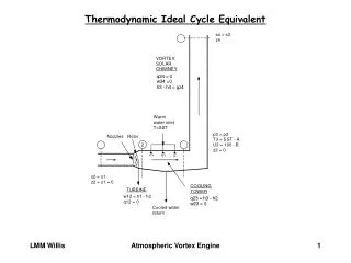
Cross-View of Regenerative Nozzleshowing temperature gradient from center of jet stream to outside of nozzle • Boundary layer protects the nozzle inner wall from seeing full temperature of hot gas. • But, it also reduces heat flux into cooling media. • Top of jet vane will see total temperature of hot gas & must be constructed of material such as Titanium. Figure obtained from: Sutton, pg 99 Thortek Expander Cycle Engine Presentation - 15 Slides
Rocket Engine Energy Balance Energy available to drive proposed expander cycle engine Figure obtained from: Sutton, George P, “Rocket Propulsion Elements”, Wiley-Interscience Publication, 4th edition, 1976, pg 40 Thortek Expander Cycle Engine Presentation - 15 Slides
J-2 Gas Generator engine vs J-2 Equivalent Expander Cycle Engine Thortek Expander Cycle Engine Presentation - 15 Slides
Thermodynamic Comparison between J-2 GG vs Expander Cycle Thortek Expander Cycle Engine Presentation - 15 Slides
OEPSS – Operationally Efficient Propulsion System Study OEPSS was a study based on lessons learned on operational processing of launch vehicles and their ground support equipment. Out of the 15 top design concerns delineated in OEPSS, the proposed engine with jet vanes will eliminate 5 concerns • Enclosed Compartments • LOX tank forward • Side Mounted Boosters • Hypergolic Systems • Hydraulic Systems • Pneumatic Systems • Pressurization Systems • Multiple Propellants • Pre-Conditioning • Excessive Subcomponent Interfaces • High Maintenance Turbopumps • Ordnance Systems • Retractable Umbilical Carrier Plates • Engine Gimbal Systems • Ocean Recovery & Refurbishment Thortek Expander Cycle Engine Presentation - 15 Slides
Further Study is needed • To determine the optimal performance characteristics of a J-2X equivalent expander cycle engine, • To determine the true manufacturing and processing costs of engines & power systems, • What design parameters or techniques should be changed in order to obtain an engine under $1M • To determine the optimal size of the jet vanes to power the J-2X equivalent expander cycle engine, • To determine optimal materials and design of jet vanes. Thortek Expander Cycle Engine Presentation - 15 Slides
Conclusion • Much more heat energy is available from regeneratively cooled jet vanes vs extending the nozzles • Jet vanes stick in the center of jet flow • Whereas an insulating boundary layer builds up along the nozzle wall • Jet vanes require far less force to operate than TVCs. • Less force = less power = smaller electric motors = smaller batteries • Up to 57% of the total fuel energy could be available to power the expander cycle turbines via the jet vanes. • Compare this 57% vs 2% available for regeneratively cooled nozzle and combustion chamber. Thortek Expander Cycle Engine Presentation - 15 Slides