Download
1 / 30
350 likes | 639 Views
Frame Relay. Semester 4, Chapter 6 Allan Johnson. Table of Contents. Frame Relay Technology Local Management Interface The Use of Subinterfaces Configuring Frame Relay. Go There!. Go There!. Go There!. Go There!. Frame Relay Technology. Table of Contents. End Slide Show.

E N D
Frame Relay Semester 4, Chapter 6 Allan Johnson
Table of Contents Frame Relay Technology Local Management Interface The Use of Subinterfaces Configuring Frame Relay Go There! Go There! Go There! Go There!
Frame Relay Technology Table of Contents End Slide Show
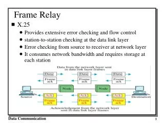
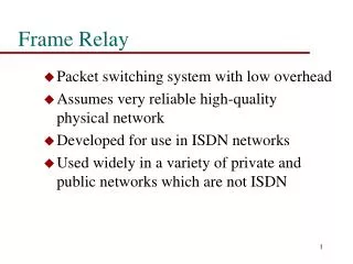
Frame Relay History • Frame Relay was designed as a stream-lined version of X.25. • X.25, a 1970s ITU-T standard, ensured reliable transport at the data link layer with error detection and error correction. • With the introduction of DoD’s TCP/IP in the early 1980s, TCP took over error correction. • Although Frame Relay detects errors at the data link layer, it does not correct. That’s now TCP’s job.
Frame Relay History • In 1990, Cisco Systems, StrataCom, Nothern Telecom and Digital Equipment (sometimes referred to as the Group of Four) worked to standardize the Frame Relay protocol and add what they dubbed LMI extensions. • Today, Frame Relay is the most popular WAN protocol because it is: • Faster than X.25, it uses TCP for error correction • Cost-effective - you no longer have to pay for a dedicated point-to-point link • Versatile - can operate over a variety of interfaces (ISDN, Serial, Dial-up, etc.)
Data Link Physical Frame Relay Operation • Devices in the Frame Relay network are the DTE (customer equipment) and DCE (provider’s frame relay switch) • Often cheaper than other technologies because many times the service provider also owns the DTE. • The Frame Relay connection between the DTE and DCE operates at the data link and physical layers of the OSI model.
Frame Relay Operation • Frame Relay operates over a permanent virtual circuit (PVC), which means that a permanent connection exists between the source DCE and destination DCE over the frame relay network. • Therefore, there is no need for call setup and termination like in ISDN. Frame Relay has two states: • Data transfer--between the DCE and the provider’s DTE • Idle--the line is active, but no data is being transferred.
Frame Relay Operation • The connection between the local DTE and the DCE in a Frame Relay network is logically identified with a Data-link Connection Identifier (DLCI). • A word about Switched Virtual Circuits (SVC) • Frame Relay over ISDN must use a SVC with ISDN’s call setup and termination procedures. • However, currently few manufacturers of DCE equipment support Frame Relay SVCs, so implementation is minimal. • Therefore, we will assume a PVC when discussing Frame Relay.
Frame Relay Lexicon • DLCI - Identifies logical connections to the Frame Relay network and has local significance only • FECN - Forward explicit congestion notification; tell receiving DTE to implement congestion avoidance procedures • BECN - Backwards explicit congestion notification; tells the sending DTE to slow down the transfer rate by 25%. • DE - Discard eligibility; bit set in the frame to say “frame is not business critical” and can be discarded • CIR - Committed information rate guaranteed by the service provider. • LMI - Local Management Interface; determines the operational status of PVCs
FECN-tells receiving DTE device to implement congestion avoidance procedures FECN BECN FRAMES DLCI-identifies logical connections on the Frame Relay switch to which the customer is attached BECN-tells sending DTE device to reduce the rate of sending data.
Frame Relay Frame Format • Flag - like most frame formats, the flag indicates the beginning and end of the frame • The DLCI makes up the first 10 bits of the address field, while the FECN, BECN, and DE bits are the last 3 bits.
Local Management Interface Table of Contents End Slide Show
LMI Overview • LMI, similar to LCP in PPP, is a set of extensions to the basic Frame Relay protocol. • LMI’s main functions are to: • determine the operational status of the PVC between source and destination. • transmit keepalives to ensure PVC stays up • inform router what PVCs are available • LMI extensions were added by the Group of Four. • A common extension that must be used by all who implement Frame Relay is virtual circuit status messages. • Optional extensions include... • Multicasting • Global addressing • Simple Flow Control
LMI Frame Format • The LMI Frame has four mandatory bytes. They are outlined in red below. Know them!!
Frame Relay Map • The term map means to “map” or bind a Layer 2 address to a Layer 3 address. • An ARP table maps MACs to IPs in a LAN • In ISDN, we use the dailer-map command to map SPIDs to IP addresses • In Frame Relay, we need to map the data link layer’s DLCI to the IP address • We use the frame-relay map command
Frame Relay Map • The Frame Relay switch builds a table of incoming/outgoing ports and DLCIs. • The router builds a Frame Relay Map through Inverse ARP requests of the switch during the LMI exchange process. • The Frame Relay Map is used by the router for next-hop address resolution.
Use of Subinterfaces Table of Contents End Slide Show
A 192.168.4.1 DLCI 16 Frame Relay Network 192.168.4.0/24 192.168.4.2 192.168.4.3 DLCI 17 DLCI 18 C B Using a Subinterface • In order to have an active Frame Relay link to all your routers in the network, you need either • All routers on the same network or subnet • or use subinterfaces All Routers in Same Network
Using a Subinterface • Rarely do you have all routers on the same network or subnet, so we use subinterfaces. • Each serial interface can logically be divided into as many subinterfaces as you need to establish PVCs with each destination. • Each destination’s DLCI needs a separate point-to-point subinterface. • Each side of the PVC must belong to the same network.
B A C S0.1 192.168.1.1 S0.2 192.168.2.1 S0.3 192.168.3.1 D Subinterface Example #1 Each PVC as a point-to-point link in its own network or subnet 192.168.1.2 192.168.2.2 192.168.3.2
A S0.17 192.168.4.1 S0.18 192.168.5.1 DLCI 16 AB-PVC AC-PVC Frame Relay Network S0.16 192.168.5.2 S0.16 192.168.4.2 DLCI 17 DLCI 18 C B BC-PVC S0.17 192.168.6.2 S0.18 192.168.6.1 Subinterface Example #2
Configuring Frame Relay Table of Contents End Slide Show
Frame Relay Encapsulation • To enable Frame Relay, simply go to the serial interface and enter the command • However, if you are connecting to a non-Cisco remote router, you must specify the option IETF Router(config)#encap frame-relay [cisco|IETF] Router(config)#int s0 Router(config-if)#encapsulation frame-relay
One Subnet/Network Configuration • The curriculum says to use a subinterface and specify multipoint. router(config-if)#int s1.1 multipoint • However, subinterfaces are not necessary when configuring PVCs on the same subnet. • Also, we do not have to set the LMI type since our Cisco IOS is 11.2 or later. LMI type is autosensed. • However, we enter a map command to link the remote rouer’s DLCI to its IP address.
A 192.168.4.1 DLCI 16 Frame Relay Network 192.168.4.0/24 192.168.4.2 192.168.4.3 DLCI 17 DLCI 18 C B One Subnet/Network Configuration • Configure frame relay encapsulation and map the destinations’ DLCIs to their IPs • Repeat the commands on each router in the network RouterA(config)#int s0 RouterA(config-if)#encapsulation frame-relay RouterA(config-if)#frame-relay map ip 192.168.4.2 17 broadcast RouterA(config-if)#frame-relay map ip 192.168.4.3 18 broadcast
Multiple Subnet/Network Configuration • When your routers are parts of different networks or subnets, then you must either physically attach them on different interfaces or use subinterfaces on a single interface. • First step is to set the encapsulation type of the serial interface and state no IP address. RouterA(config)#int s0 RouterA(config-if)#encap frame-relay RouterA(config-if)#no ip address RouterA(config-if)#no shut • Then enter subinterface configuration mode to assign each point-to-point link its IP address and define the destination’s DLCI. • Next slide shows the subinterface commands.
A S0.17 192.168.4.1 S0.18 192.168.5.1 DLCI 16 AB-PVC AC-PVC Frame Relay Network S0.16 192.168.5.2 S0.16 192.168.4.2 DLCI 17 DLCI 18 C B BC-PVC S0.17 192.168.6.2 S0.18 192.168.6.1 Multiple Subnet/Network Configuration RouterA(config-if)#int s0.17 point-to-point RouterA(config-subif)#ip address 192.168.4.1 255.255.255.0 RouterA(config-subif)#frame-relay interface-dlci 17 RouterA(config-subif)#int s0.18 (continue with configuration)
Additional Frame Relay Labs • Chapter 6 does not provide enough practice for configuring Frame Relay. • If you have an Adtran unit, use the first two labs in Chapter 8 of the Semester 6 curriculum to gain additional Frame Relay experience. • Lab 8.2.1: Configuring Frame Relay • A “One Subnet/Network” Frame Relay Configuration • Lab 8.3.4: Configuring Frame Relay with Subinterfaces • A “Multiple Subnet/Network” Frame Relay Configuration
Verifying Frame Relay • show interface serial 0 • is Frame Relay sending and receiving data? • displays both LMI and DLCI information • show frame-relay map • displays the frame relay table on the router • show frame-relay pvc • used to verify a frame relay configuration
Table of Contents End Slide Show