Download
1 / 12
120 likes | 201 Views
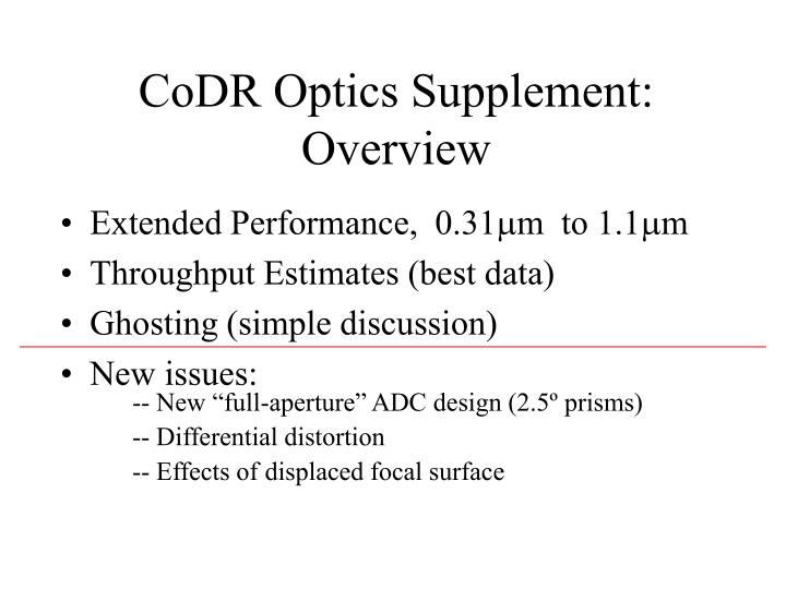
CoDR Optics Supplement: Overview. Extended Performance, 0.31 m to 1.1 m Throughput Estimates (best data) Ghosting (simple discussion) New issues:. -- New “full-aperture” ADC design (2.5º prisms) -- Differential distortion -- Effects of displaced focal surface.

E N D
CoDR Optics Supplement:Overview • Extended Performance, 0.31m to 1.1m • Throughput Estimates (best data) • Ghosting (simple discussion) • New issues: -- New “full-aperture” ADC design (2.5º prisms) -- Differential distortion -- Effects of displaced focal surface
ExtendedPerformance (0.31--1.1m) • Modeled both full- and sub-aperture designs -- there’s virtually no difference between the two for dispersion correction. • Full correction at z=60 requires increasing prism separation by 20% over current designs (planned). • Fully-corrected residuals are 0.07" rms and 0.22" pk-to-pk. • Correcting to 0.31m (vs 0.32) is easy; 1.1m most difficult. • UV PSFs are sim- ilar to 0.4m PSFs.
Corning provided numbers for UV-grade Fused Silica: result is about 1% loss for 70mm of glass at nearly all wavelengths. Sol-gel/MgF2 coatings appear fine (≤1% loss per surface), although performance below 0.4m is still calculated, not measured -- but this should simply require reducing thickness of the coatings by 20% over the 0.4--1.4m case. (0.4--1.1m GMOS Sol-gel measured by J. Stilburn.) LLNL has facilities capable of coating the prisms. Throughput Estimates: ≥95% (“est.” assumes 1% loss per surface)
Throughput, cont’d • Tuning of coatings will trade off performance in the UV vs IR. Do we want to push coatings to 0.31m (extinction)? What throughput is needed at 0.31m?
Ghost Images (Simple Discussion) • Six surface pairs potentially produce ghosts. • Ghosts involving non-parallel surfaces (4 pairs) will miss the mirror/grating (14.5°/7.25° > 5.6°). • Parallel surfaces (2 pairs) will produce ghosts at a level 10-4, but these rapidly become out-of-focus and much lower contrast. • Only the inner prism surfaces are likely to be a problem, and even there when the ghost level is above 10-6, the ghost image will appear within the PSF wings.
Spot locations measured at 9 locations and three orientations, with prism separation 850mm (full correction at Z=60), as well as null case. For each case, telescope was re-pointed to position Spot B at the field center; then a least-squares fit to translation and rotation performed. Differential Distortion Spot locations: E G I A B C D F H
Differential Distortion At non-zero angles, rotation is present (up to 0.001°)
Effects of Displaced Focal Surface • Telescope must be re-pointed (by 50", handled by guider) • Displacement of curved focal surface introduces focus tilt. (OK for LRIS if tel. focus is adjusted) • It produces dominant differ-ential distortion. (tolerable, if pointing adjusted) • Moves edge of vignetted region around edge of LRIS field (potential flat-fielding problem) • Can we correct with M2??
Spot sizes for null-ADC and no ADC are virtually identical Spot sizes measured at 9 locations and three orientations, with prism separation 850mm (full correction at Z=60) Spot Sizes Spot locations: E G I A B C D F H
ADC Spot rms-Diameters (") (calculated at 5000A)
ADC Spot 80%-Diameters (") (calculated at 5000A)