Download

1 / 15
150 likes | 350 Views
Seismic Tomography Algorithm (Hole’s Code). Omar Ochoa. Outline. Background Data Flow Diagram Research questions Status Conclusion. Background. 3-Dimensional seismic travel time tomography for determining three-dimensional velocity structure from first arrival travel time

E N D
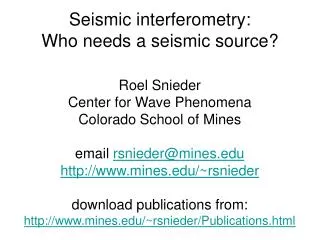
Seismic Tomography Algorithm(Hole’s Code) Omar Ochoa
Outline • Background • Data Flow Diagram • Research questions • Status • Conclusion
Background • 3-Dimensional seismic travel time tomography for determining three-dimensional velocity structure from first arrival travel time • A back-projection method • It is a non-linear tomographic procedure that minimizes computational time • provides a relatively high-resolution model • can handle structures with large velocity contrasts. • Described in: Hole, 1992, Journal of Geophysical Research, v97, 6553-6562.
Background • Implemented in Fortran and C • Wrapped with scripts • Executes in a Unix environment • Two versions of Hole’s code • Original scripts created by Hole to execute his programs • New scripts developed by Piotr Sroda to increase usability
Data Flow Diagram • Each subroutine is a process • Input and output data is piped between each process Data Flow Diagram models scripts
DFD There are 6 programs inside Hole’s Code vel1d punc cover tomosm duadd addc
DFD-1 Converts a set of data points to an equally sampled 3d velocity model
DFD-2 Calculates the first arrival travel times for each shot point using the initial velocity model
DFD-3 Calculates the ray from the shot point to the receiver and then determines how the travel time residuals affect each cell using the shot point locations within a 3D time field
DFD-4 Calculates model perturbations at each cell corner, adds the ray perturbations for all adjacent cells and averages it out to smooth it
DFD-5 Coarser smoothing of model perturbation and adds the perturbation to the 3d velocity model
DFD-6 Merge previous 3d velocity model with new velocity model
Research Questions • How can we capture Hole’s algorithm as a a workflow? • Can we expose Hole’s code as a service for other scientists? • Are there any reusable components in this workflow? • What properties are of interest to a scientist in this algorithm? • How can we provide assurance about the execution of this software service to scientists?
Status • Working on executing examples to understand how the algorithm works • Visualizing the output • Validating the output by meeting with Dr. Miller
Conclusion • There is this great piece of software that geologists want to use • Requires a lot of computer knowledge to execute • Not geology related