Download

1 / 17
170 likes | 321 Views
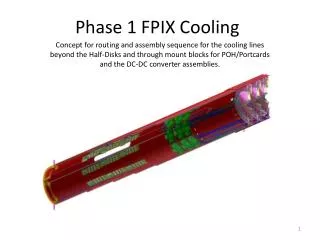
Phase 1 FPIX Insertion Check with BPIX supply tube and new beam pipe. Kirk Arndt (Purdue) with the help of Silvan Streuli, PSI for CMS FPIX Mechanical Group S. Kwan, C.M. Lei, S. Los, G . Derylo (Fermilab ) G. Bolla, D. Bortoletto, I. Shipsey, Y . Ding, V. Noe-Kim, D. Snyder ( Purdue).

E N D
Phase 1 FPIX Insertion Check with BPIX supply tube and new beam pipe Kirk Arndt (Purdue) with the help of Silvan Streuli, PSI for CMS FPIX Mechanical Group S. Kwan, C.M. Lei, S. Los, G. Derylo (Fermilab) G. Bolla, D. Bortoletto, I. Shipsey, Y. Ding, V. Noe-Kim, D. Snyder (Purdue) Installation and Beampipe
Simplified model of FPIX upgrade service cylinder (SC) ready for insertion Simplified model of BPIX upgrade barrel section and Supply Tubes (ST) New rail extensions required for upgrade FPIX FPIX SC fully inserted Installation and Beampipe
FPIX SC rear support foot BPIX supply tube FPIX SC forward support foot (located at forward end of the stiff, double-walled SC section) Installation and Beampipe
The end of the BPIX supply tube will be moved outwards by 38mm after installation • The envelop for the pixels inside the Tracker in a 2007 CAD model (see backup slide) allows the BPIX supply tube to swing out by an additional 7.75mm. Only a test installation at Point 5 can show if this theoretical space is really available. • It's possible that the heavy cabling at the end of the BPIX supply tube may prevent us from swinging the supply tube by this additional distance. Installation and Beampipe
Insertion position 1 • Z = 2525 mm • Minimum Clearance: 3.3 mm 8.9 mm • Note: • clearances are listed with BPIX ST backend • moved 38mm 45.75mm Installation and Beampipe
Insertion position 2 • Z = 2275 mm • Minimum Clearance: 5.4 mm 7.4 mm Installation and Beampipe
Insertion position 3 • Z = 2050 mm • Side Clearance: 5.5 mm 11.6 mm • Minimum Clearance: 1.8 mm 3.8 mm Installation and Beampipe
Insertion position 4 • Z = 1630 mm • Minimum Clearance to Beam pipe support collar 4.9 mm 4.9 mm 4.9mm Installation and Beampipe
Insertion position 5 • Z = 1077 mm • Side Clearance: 5.9 mm 8.6 mm • Minimum Clearance: 2.0 mm 2.8 mm Installation and Beampipe
Insertion position 6 = final installed position • Z = 290.4 mm • Top Clearance: 4.7 mm 4.7 mm • Minimum Clearance: 4.0 mm 4.0 mm Installation and Beampipe
Moving the front support towards IP FPIX SC rear support foot BPIX supply tube FPIX SC forward support foot (located as far forward as possible) • Option to locate FPIX SC forward support foot as far forward as possible. • This increases the clearance between FPIX and BPIX throughout installation, and does not change the clearance between FPIX and the beam pipe support collar. Installation and Beampipe
Summary of minimum clearances during phase 1 FPIX insertion Installation and Beampipe
For FPIX, the beam pipe support collar design is a critical issue, especially when the beam pipe is misaligned! • The support collar design should be as sleek as possible(see image of an idea shown below/right). • Some of the beam pipe collar designs proposed in the past are too bulky. A collar with a length (along beam pipe) of 10mm, but with a thickness of only 1mm (cross section) in the critical area would be ideal. Installation and Beampipe
Minimum clearances as the forward end of upgrade FPIX overlaps the latest beam pipe support collar design clearance to the support collar …and to the pin in the support collar • The closest approach is between the face of the pin in the collar for fastening the vertical support wires and the ends of the inner rings of the half-disks(right-hand picture above) Installation and Beampipe
Options to increase clearance during insertion of FPIX Find a rail extension shape that optimizes the FPIX installation = DONE Increasing the inner radii of the BPIX supply tube = not possible…already suffer from very little space to integrate all the necessary components. Modify the outer shape of FPIX= don't see an easy change to the outer shape of the forward end of the new FPIX to create more clearance. Move backend of BPIX supply tube out by an additional 7.75mm = may not be possible, and does little to increase clearance during insertion beyond beam pipe supports. Make the beam pipe support collar design as sleek as possible. Move the FPIX SC front support towards IP = best design option. Make the front pins movable (spring loaded?) in case of a contact between FPIX SC and BPIX ST, so the FPIX SC can move slightly towards the beam pipe…? Installation and Beampipe
Backup slide Installation and Beampipe
Information from Silvan Streuli, PSI – Feb2012 Installation and Beampipe