Download
1 / 1
10 likes | 75 Views
Improving Laser/Plasma Coupling with Rough Surfaces. K. Highbarger 1 , R. Stephens 2 , E. Giraldez 2 , J. Jaquez 2 , L. VanWoerkom 1 , R. Freeman 1

E N D
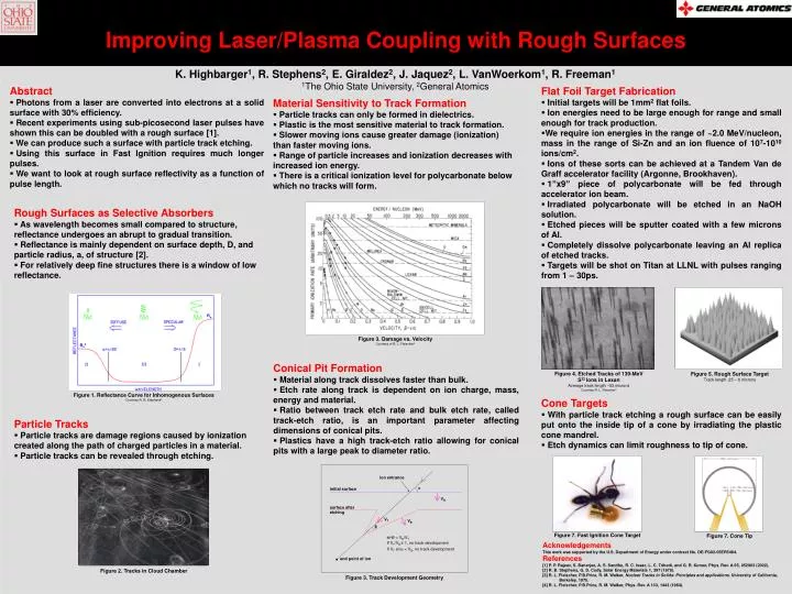
Improving Laser/Plasma Coupling with Rough Surfaces K. Highbarger1, R. Stephens2, E. Giraldez2, J. Jaquez2, L. VanWoerkom1,R. Freeman1 1The Ohio State University, 2General Atomics • Abstract • Photons from a laser are converted into electrons at a solid surface with 30% efficiency. • Recent experiments using sub-picosecond laser pulses have shown this can be doubled with a rough surface [1]. • We can produce such a surface with particle track etching. • Using this surface in Fast Ignition requires much longer pulses. • We want to look at rough surface reflectivity as a function of pulse length. • Flat Foil Target Fabrication • Initial targets will be 1mm2 flat foils. • Ion energies need to be large enough for range and small enough for track production. • We require ion energies in the range of ~2.0 MeV/nucleon, mass in the range of Si-Zn and an ion fluence of 107-1010 ions/cm2. • Ions of these sorts can be achieved at a Tandem Van de Graff accelerator facility (Argonne, Brookhaven). • 1”x9” piece of polycarbonate will be fed through accelerator ion beam. • Irradiated polycarbonate will be etched in an NaOH solution. • Etched pieces will be sputter coated with a few microns of Al. • Completely dissolve polycarbonate leaving an Al replica of etched tracks. • Targets will be shot on Titan at LLNL with pulses ranging from 1 – 30ps. • Material Sensitivity to Track Formation • Particle tracks can only be formed in dielectrics. • Plastic is the most sensitive material to track formation. • Slower moving ions cause greater damage (ionization) than faster moving ions. • Range of particle increases and ionization decreases with increased ion energy. • There is a critical ionization level for polycarbonate below which no tracks will form. • Rough Surfaces as Selective Absorbers • As wavelength becomes small compared to structure, reflectance undergoes an abrupt to gradual transition. • Reflectance is mainly dependent on surface depth, D, and particle radius, a, of structure [2]. • For relatively deep fine structures there is a window of low reflectance. Ro Figure 3. Damage vs. Velocity Courtesy of R. L. Fleischer3 Ro2 • Conical Pit Formation • Material along track dissolves faster than bulk. • Etch rate along track is dependent on ion charge, mass, energy and material. • Ratio between track etch rate and bulk etch rate, called track-etch ratio, is an important parameter affecting dimensions of conical pits. • Plastics have a high track-etch ratio allowing for conical pits with a large peak to diameter ratio. Figure 4. Etched Tracks of 139-MeV S32 Ions in Lexan Average track length ~53 microns Courtesy R. L. Fleischer4 Figure 5. Rough Surface Target Track length .25 – 6 microns Figure 1. Reflectance Curve for Inhomogenous Surfaces Courtesy R. B. Stephens2 • Cone Targets • With particle track etching a rough surface can be easily put onto the inside tip of a cone by irradiating the plastic cone mandrel. • Etch dynamics can limit roughness to tip of cone. • Particle Tracks • Particle tracks are damage regions caused by ionization created along the path of charged particles in a material. • Particle tracks can be revealed through etching. ion entrance α initial surface VB surface after etching VT VB θ Figure 7. Cone Tip Acknowledgements This work was supported by the U.S. Department of Energy under contract No. DE-FG02-05ER5484. Figure 7. Fast Ignition Cone Target sinθ = VB/VT If VT/VB ≤ 1, no track development References [1] P. P. Rajeev, S. Banerjee, A. S. Sandhu, R. C. Issac, L. C. Tribedi, and G. R. Kumar, Phys. Rev. A 65, 052903 (2002). [2] R. B. Stephens, G. D. Cody, Solar Energy Materials 1, 397 (1979). [3] R. L. Fleischer, P.B.Price, R. M. Walker, Nuclear Tracks in Solids: Principles and applications. University of California, Berkeley, 1975. [4] R. L. Fleischer, P.B.Price, R. M. Walker, Phys. Rev. A 133, 1443 (1964). If VT sinα < VB, no track development end point of ion Figure 2. Tracks in Cloud Chamber Figure 3. Track Development Geometry