Download
1 / 11
110 likes | 233 Views
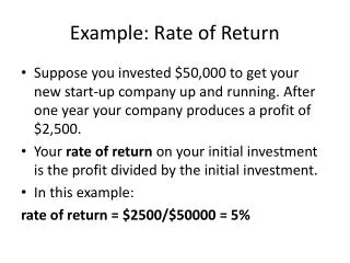
David Therkelsen and L. Richard Carley Department of Electrical and Computer Engineering Carnegie Mellon University Pittsburgh, PA 15213. Example Simulation of High Data Rate Limitations of Head-Electronics Interconnect. Data Storage Systems Center. Carnegie Mellon University.

E N D
David Therkelsen and L. Richard Carley Department of Electrical and Computer Engineering Carnegie Mellon University Pittsburgh, PA 15213 Example Simulation ofHigh Data Rate Limitations ofHead-Electronics Interconnect Data Storage Systems Center Carnegie Mellon University
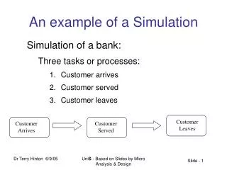
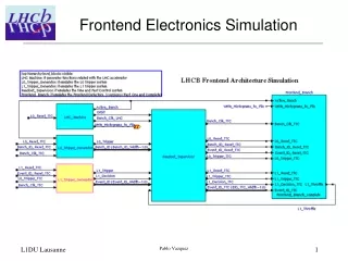
Head / Electronics Interconnection Write Driver to Write Head and Preamp to Read Head Where is the IC? Back near pivot point (standard location) Could move out closer to head Thermal / heat problem cost problem (either 1 per flexure or 1/2 per flexure) For 3.5” disk drive typical length is about 50mm Time of flight - 150cm/ns signal - reflects off head - reflects off writer -- total 0.66ns Primary Impact Prior data edges reflecting back and forth can add or subtract Changes the actual zero crossing time of the head field Changes the time derivative of the head field at the zero crossing data dependent position and width variations Interconnect Limits Data Rate?
Termination of transmission line is head: nonlinear and frequency dependent element frequency domain analysis not possible (linear superposition fails) time-domain transient analysis does work (a.k.a. SPICE tran analysis) Construct circuit-model for head take model from literature (Klaassen and Hirko, 1996) model electrical terminal nonlinearity model conversion process to write field One Trick - Modeling Saturating Nonlinearities Started using polynomial spline implementation provided by simulator Result was extremely bad convergence Developed saturating nonlinearity model based on transistors The circuit simulator has been tuned for transistors Fast efficient transient simulations Can fit any arbitrary static nonlinearity Nonlinear Write Head Model
Nonlinear Head Circuit Model Electrical Input Model Time Derivative for Back EMF Voltage Sources Yoke Saturation Model
Write Flux Nonlinear Head Circuit Model Yoke Time Response Model Vdd Pole Tip Saturation Circuit
Model Order Reduction: Discrete segmentation (currently using 10 segments) Eliminate frequency dependence due to skin effect we can’t put L() and R() into our circuit simulator Skin Effect - function of frequency but not amplitude L() - skin effect decreases inductance at high frequencies R() - skin effect increases resistance at high frequencies C/2 - frequency independent Interconnect Model R() L() R() L() R() L() R() L() C / 2 C / 2
Approximate frequency dependence due to skin effect Use addition frequency independent elements Start with a first order approximation for transmission line segment Used transmission line presented at TMRC-97 Balakrishnan and Carpenter They extracted C, R(), and L() per unit length Conductors Insulator Ground Plane Frequency Independent Model R2 L2 R() L() R1 L1 C / 2 C / 2 C / 2 Transmission Line Model C / 2 Single-ended Equivalent Circuit
Inductance / unit length of interconnect vs. model Fit of First Order Model - L()
Resistance / unit length of interconnect vs. model Fit of First Order Model - R()
Combining all of the Pieces 50u x 10u lines on 100u polyimide over ground plane 50mm long Transient Simulation Result
There Can Be a Data Rate Limit Set by Interconnect Depends on length and type of interconnect Depends on head Prescriptions Decrease overall capacitance of interconnect Characterize signal dependence of timing offset and gradient vs. interconnect parameters (using commercial 2-D FEA tools) symbol rate terminations (at electronics end and at write head end??) Needs: Range of allowable interconnect geometries and relevant data Parameters for “future” generation nonlinear write head models Summary