Download

1 / 24
240 likes | 247 Views
FLOFAB Energy Savings. Via pump optimisation and VFD. Use Energy Consumption. Pump Systems Have Greatest Energy-Saving. The System: What is a System Curve?.

E N D
FLOFAB Energy Savings Via pump optimisation and VFD
The System: What is a System Curve? A system curve represents the sum of the static head and the friction loss due to flow of fluid through a system. The pumping system will operate where the pump and system curves intersect System curves help demonstrate pumping system behavior in a graphical manner If a system curve can be determined, it can help identify the effects of pump and/or system modifications
System Optimization and Improvement Opportunities •Eliminate unnecessary uses • Improve piping configuration • Consider alternative pump configurations • Change pump speed•Using a pump when the fluid is not needed• Running two pumps when only one is needed• Excessive pump head or flow
Best Energy Efficiency using VFD Because we know the affinity rules, we notice that key variable is speed.VFD (Variable Frequency Drive): Electronic unit that varies the fixed mains voltage & frequency to control the speed of standard a.c. electric motors
Throttling valve – duty flow Head Energy Consumed Aim for operation at best efficiency point for lowest energy consumption Flow
Throttling – reduced flow Head Discharge pressure increases and only a small reduction in energy. Energy Consumed Flow
Throttling valve – low flow Head Some savings in energy but high temperature rise in pump housing & reduction in bearing & seal life) Energy Consumed Flow
Pump Reliability andBEP Proprietary and Confidential of HydraulicInstitute
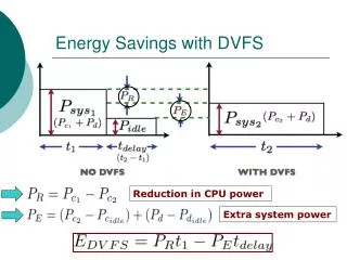
Typical energy savings with VFD on centrifugal pumps • Flow is proportional to speed • Power varies to the cube of the speed change • 20% reduction in speed = 50% reduction in energy • 50% reduction in speed = 80% reduction in energy
Throttling valve compared to VFD • VFD gives ~35% energy savings compared to throttling valve (On typical variable flow applications) Control with valves Control with VSD
Motor starting current & torque (As a % rated motor torque on typical centrifugal water pump) Direct on line start VFD start Starting current ~500-600% ~30-40% • VFD start • Significantly lower starting current & torque • Controlled acceleration & deceleration (adjustable ramp up & down times) • Very smooth starting & stopping Starting torque ~ 250-350% ~30-40%
Energy consumption of single & multiple pump systems @ same flow Single VFD controlled pump 100% Standard cascade control with 1 x VFD pump & multiple fixed speed pumps 53% 48% 43% Master – follower with 1 x VFD per pump Note: kWh figures are approximate relative %, based on sample test • Master follower = best energy efficiency
Avoid Sensorlessin Boosters Because this relation between power/pressure/flow exist, we can estimate head pressure and flow from a single motor power data. That is not valid for the total system pressure and flow.Additionnalcontroller would be used to sum data from drive 1 and 2, system becomes complex and hard to debug. It will look to combine data fromM1 – M2 – M3. As for sensor read perfectly system pressure
AEO can not be used with sensorless Automatically reduces motor voltage at light load Reduces motor current draw Reduces motor power consumptionReason it does not work with AEO: Since Power and speed is used to estimate Pressure or flow, Power can not vary, AEO optimise power.
Possible retrofit • Look at existing applications • Install turn key panels • Protect exsiting motors or update with new. Update features with KW counters Etc..