Download
1 / 21
210 likes | 248 Views
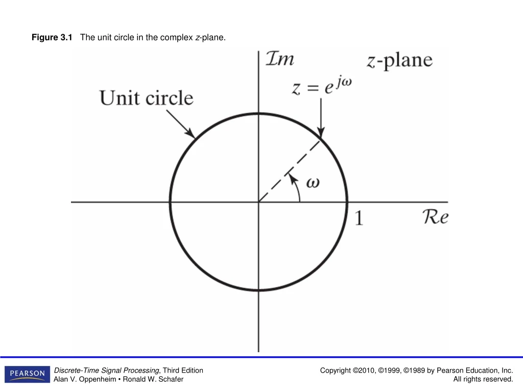
Figure 3.1 The unit circle in the complex z -plane. Figure 3.2 The ROC as a ring in the z -plane. For specific cases, the inner boundary can extend inward to the origin, and the ROC becomes a disc. For other cases, the outer boundary can extend outward to infinity.

E N D
Figure 3.2 The ROC as a ring in the z-plane. For specific cases, the inner boundary can extend inward to the origin, and the ROC becomes a disc. For other cases, the outer boundary can extend outward to infinity.
Figure 3.5 Pole–zero plot and ROC for the individual terms and the sum of terms in Examples 3.3 and 3.4. (a) 1/(1 − 1/2z−1), |z| > 1/2. (b) 1/(1 + 1/3z−1), |z| > 1/3. (c) 1/(1 − 1/2z−1) + 1/(1 + 1/3z−1), |z| > 1/2.
Figure 3.7 Pole–zero plot for Example 3.6 with N = 16 and a real such that 0 < a < 1. The ROC in this example consists of all values of z except z = 0.
Figure 3.8 Examples of four z-transforms with the same pole–zero locations, illustrating the different possibilities for the ROC, each of which corresponds to a different sequence: (b) to a right-sided sequence, (c) to a left-sided sequence, (d) to a two-sided sequence, and (e) to a two-sided sequence.
Figure 3.9 Pole–zero plot for the system function in Example 3.8.
Figure 3.11 Pole–zero plot for the z-transform in Example 3.10.
Figure 3.12 Pole–zero plot for the z-transform of the convolution of the sequences u[n] and anu[n] (assuming |a| < 1).