Download
1 / 30
300 likes | 305 Views
Kapitel 19: Routing. Kapitel 21: Routing Protocols. Hosts and Routers. The computers in Internet terminology are called hosts . They usually have one NIC (network interface card = network adapter = nätverkskort) Routers are special purpose computers and they have more than one NIC

E N D
Kapitel 19: Routing. Kapitel 21: Routing Protocols
Hosts and Routers • The computers in Internet terminology are called hosts. They usually have one NIC (network interface card = network adapter = nätverkskort) • Routers are special purpose computers and they have more than one NIC • An old name for routers is gateways • Forward packets between networks (route and switch) • Transform packets as necessary to meet standards for each network • A Windows PC can act as a router if it has more than one NIC, and IP forwarding is enabled in the networking settings.
What Does a Router Do? • Accepts incoming packets • Checks the destination address in the IP header • Look up for destination in the forwarding table • Sends packet to the appropriate next hop • The packet may be dropped if • There is no space in the router’s buffers • The TTL=0 • There is no matching row in the routing table
Forwarding (Routing) Table • The forwarding table consists of two columns: “Destination network” and “Next hop”. • Destination network is some network address and the next hop is the address of the next router. • When the router is connected directly to a network, the “Next hop” is labeled as “Direct” meaning “Directly connected”
Default Route • In order to make the forwarding table shorter (smaller number of rows) the default route is introduced • “Default” or “Else” is a row that points to some “Next hop” and is used whenever a destination is not found in the forwarding table. • Hosts send all packets out of their network to the default router (or gateway)
Example 10 Using the table in Figure 19.32, the router receives a packet for destination 192.16.7.1. For each row, the mask is applied to the destination address until a match with the destination address is found. In this example, the router sends the packet through interface m0 (host specific).
Example 11 Using the table in Figure 19.32, the router receives a packet for destination 193.14.5.22. For each row, the mask is applied to the destination address until a match with the next-hop address is found. In this example, the router sends the packet through interface m2 (network specific).
Example 12 Using the table in Figure 19.32, the router receives a packet for destination 200.34.12.34. For each row, the mask is applied to the destination address, but no match is found. In this example, the router sends the packet through the default interface m0.
Example: Unicast Routing Host with IP address 128.47.92.67 sends a packet to host 128.47.23.10 Router R1 checks its table and sends it to R2 through its interface 2. Router R2 checks its table and sends it to its interface 1 128.47.23.10 128.47.23.00 /24 1 R2 2 128.47.92.67 R3 2 1 R1 3 128.47.36.00 /24 128.47.36.97
The Forwarding Table • Necessary in every host and the router • On Windows OS it can be seen using the command netstat –rn at the command prompt • Entries in the destination column are networks, not hosts • Once the interface on the router through which the packet is to be delivered is known, the physical address is used for delivery • Contains the columns: Destination (Network destination), Mask (Netmask), Next hop (Gateway), Interface and Metric
How Routers Build the Routing Tables • Preprogrammed or Static Routes • The table is manually configured by a human • The routes cannot be dynamically changed if something fails • Dynamically calculated routes • Calculated by the software built in the routers that provide communication among routers • Algorithms that calculate shortest path are used • Complexity is increased, but the routes change automatically if some part of the network fails
Metric • A metric is a cost assigned for passing through a network • The total cost of the path is the sum of the metrics for the networks that are on the path • Metrics are assigned in such a way that the “best pat” is the path with the minimum total cost
The “Best Path” The “best path” from S to D is A C B • Factors determining the best path • Bandwidth • Delay • Hop-count • Load • Money • Reliability • The cost or the metric can involve a single or several of these factors B S D A 4 C 1 2
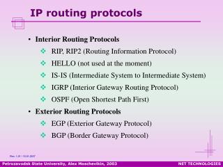
Interior vs. Exterior Protocols • The worldwide Internet is a very large network • It needs to be segmented in areas based upon the entity that administrates the networks and routers in the area • Autonomous System (AS) is a collection of networks and routers under single administration authority • Interior protocols or IGP (Interior Gateway Protocols) • Used for routing inside AS • Exterior protocols or EGP (Exterior Gateway Protocols) • Used for routing between ASs
Figure 21.5 Initial routing tables in a small autonomous system
Interior Routing Protocols • The goal: To choose the best path, among a set of alternatives based on some or a combination of criteria (e. g. minimum delay, maximum throughput etc.) • The objectives are to use the network resources (bandwidth and the router’s buffers and processing power) in the best way • Two groups of interior protocols • Distance Vector protocols • Link State protocols
Figure 21.2Popular routing protocols RIP = Routing Information Protocol OSPF = Open Shortest Path First BGP = Boarder Gateway Protocol
Unicast vs. Multicast • Unicast: • One source to one destination • Multicast: • One source to many destinations • Many sources to many destinations • Many sources to one destination • Motivation for multicast routing • Growing demand (vide/audio conferences, vide streaming etc) • Bandwidth need to be saved
Example Router 3 Receiver 1 Router 1 • If unicast routing is used, the links between the sender and the Router 1 will be overloaded (bandwidth required will depend on the number of receivers) Receiver 2 Sender Router 2 Receiver 3
Group Membership vs. Multicast Routing • IGMP (Internet Group Management Protocol) • Keeps router up-to-date with group membership of entire LAN • A device can join or leave a group at any moment • Multicast Routing Protocols • MBone – A set of routers on the Internet that are running multicast routing protocols • Tunneling (encapsulation of multicast packets into unicast packets) is used in the rest of the network
Note: In multicast routing, the router may forward the received packet through several of its ports.
Note: IGMP is a group management protocol. It helps a multicast router create and update a list of loyal members related to each router interface.