Download

1 / 40
400 likes | 547 Views
Fuel Cells: At the Brink of Change. The Push Toward Fuel Cells. Environmental Benefits CO 2 levels (40% – 60% less than gas turbine) Very low SO x , No x , and particulate production

E N D
The Push Toward Fuel Cells • Environmental Benefits • CO2 levels (40% – 60% less than gas turbine) • Very low SOx, Nox, and particulate production • Electrical Eff. and possible contribution to heating loads and selling back to grid (total possible conversion of 90% for energy contained in fuels) • Possible CO2 sequestration • Long-term energy solution possible • Many diffferent possible fuels • Hydrocarbons, gasified coal, alcohols, pure hydrogen, and water (?) • Others • Quiet • Longevity and dependability • Cogeneration/Distributed Power: transmission losses
Fuel Cell History • Fuel Cells are not a myth or dream! • Research interest peaks during oil price climes • Initial research in 60’s and early 70’s. • First use by military and NASA • Current push by DOE and DOD to commercialize production • Corporate cooperation with AlliedSignal Aerospace Company, Analytical Power Corporation (Boston), Avista Laboratories, ONSI Corporation, Siemens/Westinghouse,etc. • Over 30 organizations/universities/companies. • Current use world-wide about 1000 +/- 500
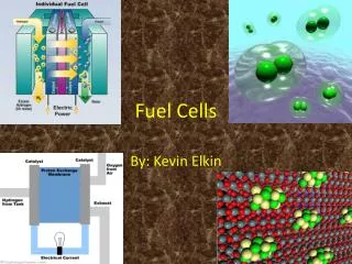
Fuel Cell Technical Concept • Similar to battery design • Fuel Cell is a “continuous-feed battery” • Most oxidize hydrogen at anode and reduce oxygen at cathode. Ionic Conductive Electrolyte separates the poles. Each system consisting of these components is called a “cell” • Hydrogen is obtained via reactions involving common hydrocarbon fuels (CO2 is in fact produced in process) • To obtain useful energy, cells are arranged in units called stacks (Bipolar plate concept) • Fuel Cells, when arranged in stacks, can produce from several watts to 10 MW or more as in conventional power plants. Size of stack varies with the required load.
Fuel Cell Classifications • low- (25 –100o C), medium- (100 – 500o C), High- (500 – 1000o C), and very high-temperature (1000+o C) • Types of fuels • Direct hydrogen-oxygen, organic-oxygen, nitrogenous-oxygen, hydrogen-halogen, metal-oxygen • Current research targets H2/O2 fuel cells • Types of electrolyte: standard classification • Alkaline (AFC), phosphoric acid (PAFC), polymer electrolyte (PEMFC), molten carbonate (MCFC), solid oxide (SOFC), others • Current research targets these 5 types
Complete Energy Production Process • Step 1: Hydrocarbons converted to H2 and CO2 • At operation Temp < 600 C, hydrocarbons need “reformed” before entering fuel cell to obtain H2 and CO2 by-product. • Two-stage reformation. • Ex: (1) CH4 + H2O CO + 3H2 (higher temp) (2) CO + H2O CO2 + H2 (lower temp) • 2nd stage eliminates CO, which poisons FC catalyst. • Reformer reactions are endothermic, requiring excess heat from within fuel cell or from burning exhaust fuel. Operating temp of 800 – 900o C. • Reformer is 85 – 98% in fuel conversion Eff. • Reformer system comprises at least 75% of total unit cost. • AFC, PEMFC, and PAFC all need reformers.
(Step 1 Continued) • At Temp > 600 C, fuels spontaneously convert into H2 and CO2. • Fuels fed directly to fuel cell anode • Reformers no longer necessary • Fuel conversion Eff. around 90% • MCFC and SOFC don’t require a reformer.
Second Step: Fuel Cell Reactions • Anode: • H2 diffuses from gaseous feed to electrolyte • H2 diffuses through electrolyte to catalyst surface • H2 adsorbs to catalyst and associates for ionization • H2 activation energy for disassociation is lowered and H2 is ionized in presence of electrolyte • H+ ions travel through electrolyte solution to cathode for reaction with O2 • Electrons travel through anode and integrate with circuit. • Cathode: • O2 diffuses from air feed onto catalyst surface • O2 adsorbs to catalyst and associates with neighboring electrolyte-H+ complex. • Overall reaction, after formation of several intermediates, involves reduction of O2 and reformation of water (or –OH). • O2 reduction is kinetically slow, hence, economic and technical limiting step due to high bond strength present in O2 • Electrolyte ionically travels to anode/cathode sites through the electrolyte for reaction • All FC’s give off heat in reaction of H2
Third Step: (Optional) Power Conditioning • DC power created by FC must be converted to AC via a power conditioner. • Miscellaneous Design Variables • H2 feed compressor – higher conversion • Heat transfer units – increase overall efficiency by withdrawing heat produced by reaction and electric resistance losses • Use by building • Use within system for generation of steam in reforming or for heat in endothermic hydrocarbon shift to CO and H2 • Recirculation of hot gases within system • Heat transfer conduits in bipolar plates • Blowers and fans • Gas-turbine system in series with fuel cell to capture energy of exiting flue/reformed gases
Top Left: 250 kW Ballard Generation Systems’ natural gas fuel cell at Crane Naval Surface Warfare Center. Bottom Left: Fuel Cell Inc. 250 W Direct Fuel Cell at headquarters, powering company during day and grid during night. Top Right: H Power unit sold in NE U.S. for storms/power failures. Couldn’t keep up with high demand.
Top Left: Siemens-Westinghouse 220 kW SOFC/gas turbine unit at Univ. of Cal – Irvine. Total electrical Eff. of 58%. Bottom Left: Siemens-Westinghouse SOFC unit in Netherlands providing 110 kW of electricity to grid and 64 kW of heat to district heating system. 46% electrical Eff. Bottom Right: Hyrdogenics portable PEMFC system that can operate between –50 and 40 Celcius
Phosphoric Acid Fuel Cell (PAFC) • Fuels: Reformed hydrocarbons, gasified coal. • 180 – 250oC operating temp. • Indirect Fuel Cell • Closest FC technology to commercialization. Possibilities include: • Dispersed power plants (5 – 20 MW) using hydrocarbons • On-site cogeneration plants (50 – 1000 kW) • 600 – 800 mV/cell • Expected plant lifetime of stack is 40,000 hours (4.5 yrs) with 5–7% efficiency loss.
Reactions Anode: H2 2H+ + 2e- Cathode: ½ O2 + 2H+ + 2e- H2O Overall: H2 + ½ O2 H2O Nernst Equation: N.A.
PA is an excellent electrolyte: thermal, chemical & electrochemical stability Simple construction: carbon, PTFE & SiC Cell Eff = 50% Power plant eff. = 40% Slow oxygen reduction kinetics: noble metal catalysts necessary (major econ. limitation) Double reforming process (steam and shift reaction) Carbon base of cathode degrades over lifetime in high temp. or over 0.8V (major econ. limitation) Loss of Pt surface from sintering Advantages Disadvantages
Molten Carbonate FC (MCFC) • Fuels: Hydrocarbons, gasified coal, methanol, naphta • 650o C optimal operating temp. (lifetime and conversion to H2) • Direct Fuel Cell • Expected commercialization 5 years after PAFC. Possibilities include: • Cogeneration • Coal-fired baseload electric utility plants • 750 – 950 mV/cell • Degradation of 5 mV/1000 hr. • Lifetime unconfirmed: 10,000+ hrs.
Reactions • Reforming at Anode: • CH4 + H2O 3H2 + CO • 3H2 + 2CO32- 3H2O + 3CO2 + 6e- • CO + CO32- 2CO2 + 2e- • Overall: CH4 + CO32- 2H2O + 5CO2 + 2e- • Anode: (1) H2 + CO32- H2O + CO2 + 2e- • (2) CO + CO32- 2CO2 + 2e- (minor) • Shift: CO + H2O H2 + CO2 • Cathode: ½ O2 + CO2 + 2e- CO32- Nernst Equation:
Internal fuel reforming High temp. elec. Efficiency & waste heat transfer Rapid kinetics CO2 recycle Greater fuel flexability and overall Eff. over PAFC 100% fuel reformation highest possible cell voltage Cooling load eliminated by internal reforming Noble metal catalysts at electrodes (major economic limitation) Reforming of fuel gas for CO removal Heat leakage Corrosion lifetime Slow O2 reduction Ni dissolution causing cathode reduction and anode deposition Carbon deposition on anode Advantages Disadvantages
Solid Oxide FC (SOFC) • Fuels: hydrocarbons, alcohols, gasified coal, diesel oil, naphta, coal gas. • 1000oC operating temperature • Direct Fuel Cell • Potential Uses: • Coal gasification plants, industrial & utility power, commercial buildings • 35,000 hours (4.0 yrs) of run-time achieved • 3 types of cell design: tubular (Westinghouse), flat-plate (Ztec Ceramatec), or monolithic (Allied Signal)
Reactions Anode: (1) H2(g) + O2- H2O(g) + 2e- (2) CO(g) + O2- CO2(g) + 2e- Combined Anode: aH2(g) + bCO(g) + (a+b)O2- aH2O(g) +bCO2(g) + 2(a+b)e- Overall Cathode: ½(a + b)O2 (g) + 2(a + b)e- (a+b)O2- Overall Cell Reaction: ½(a+b)O2(g) + aH2(g) + bCO(g) aH2O(g) + bCO2(g)
Elec. Eff. Over 80% High-grade heat available High tolerance to fuel impurities (sulfur) Simplfication: No CO2 recycle necessary No catalysts: quick oxidation/reduction 96% of theoretical voltage maintained Solid oxide electrolyte very durable/reliable 6% less efficient than MCFC in terms of maximum voltage output (equilibrium conversion) Needs 5 – 10 year lifespan for commercialization: corrosion effects Advantages Disadvantages
Environmental Analysis • Emissions • Fuels with highest H to C ratios are best for low CO2 emissions (petroleum, methanol, natural gas) • Because fuel cells demand clean fuel for correct operation, their emissions are very low by default • Very low NOx emissions from PAFC because tail gas is burned for heat for fuel processor • Very low NOx emissions in MCFC because anode gas passed by cathode, which effectively scrubs NOx compounds • Overall economic benefit in preventing capital costs of product gas cleansing equipment
Other Green Aspects • Acoustic Emissions: Noise level at 30 m from a PAFC unit is 55 dB • Equivalent to a household air conditioner • Low amounts of waste heat (as opposed to the Carnot cycle • Heat not used for cogeneration can be dumped into air • Prior two facts make the fuel cell ideal for use in urban, residential, and isolated areas • Dismantling of cells and reclamation of parts after end of lifespan will definitely occur because of the economic value of catalysts (particularly Pt), electrolytes, electrodes, and support materials (ceramics)
Current FC Economics • Positive Economics/Performance • Strong DOE funding and support • Some authors estimate cost of air pollutants to be 13% of GNP • Carbon Dioxide tax? • Proposed in Germany • Collection of CO2 by reformers • Twice as efficient as conventional plants even without cogeneration • Peak oil production expected between 2010 and 2020: • Definitely not 100 years of oil remaining • fuel cells will provide significant energy for U.S. • Variety of fuels capable of reformation or use in IRFCs • Modularity in mass production and efficiency • Partial load efficiency • No voltage spikes/current oscillations w/ cogeneration
Difficulties in economics • Gasoline Infrastructure difficult to reverse. • Consequently, methanol and methane infrastructure difficult to establish • Most important current costs to overcome • Capital cost • Stack replacement costs and O&M • FC fuel costs/kW compared to gas turbine fuel costs/kW
Current Performance • 20 – 40% energy service cost savings over conventional energy service in large buildings • 36% of U.S. energy consumption by building sector • Residential units available for $3000-$5000/6 kW • Small-Scale FC Commercialization Group: • $0.07/kW for methane and $0.11/kW for propane in residential fuel cells • Compared to $0.03/kW to $0.15/kW throughout U.S. • Conclusion: best economic performance in areas of high electricity costs and low methane costs (California!) • Power plant PAFC from ONSI Corp: $4000/kW • Economics improved by several adjustments • Cogeneration with water and space heating • Electricity sold back to the grid • Production of hydrogen during off-peak hours and energy storage for peak loads
Anticipated Performance • 2nd generation (2003) FC performance targets • $1000 - $1500/kW total cost • 50 – 60% efficiencies • 21st century FC performance targets • Stack cost of $100/kW • Total system cost of $400/kW • 70 – 80% efficiencies • Near-zero emissions
The Future • Water Fuel Cells • This is a myth (currently) • no catalysts known can decompose water at a sufficient rate • Current method of splitting water is electrolysis: obvious problem • No mechanism even found in research • Possibly H2O H2 + 1/2O2 (energetically unfavorable at standard conditions)