Download
1 / 37
370 likes | 376 Views
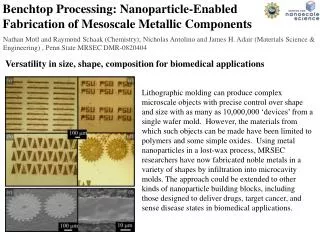
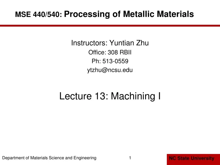
MSE 440/540: Processing of Metallic Materials. Instructors: Yuntian Zhu Office: 308 RBII Ph: 513-0559 ytzhu@ncsu.edu Lecture 13: Machining I. Machining.

E N D
MSE 440/540: Processing of Metallic Materials Instructors: Yuntian Zhu Office: 308 RBII Ph: 513-0559 ytzhu@ncsu.edu Lecture 13: Machining I 1
Machining • Cutting action involves shear deformation of work material to form a chip, and as chip is removed, new surface is exposed: (a) positive and (b) negative rake tools
Machining Operations • Most important machining operations: • Turning • Drilling • Milling • Other machining operations: • Shaping and planing • Broaching • Sawing
Turning and Drillng • Used to create a round hole, usually by means of a rotating tool (drill bit) with two cutting edges • Single point cutting tool removes material from a rotating workpiece to form a cylindrical shape https://www.youtube.com/watch?v=Mn9jpqI8rao&feature=related
Milling • Rotating multiple-cutting-edge tool is moved across work to cut a plane or straight surface • Two forms: (c) peripheral milling and (d) face milling
Cutting Tool Classification • Single-Point Tools • One dominant cutting edge • Point is usually rounded to form a nose radius • Turning uses single point tools • Multiple Cutting Edge Tools • More than one cutting edge • Motion relative to work achieved by rotating • Drilling and milling use rotating multiple cutting edge tools
Cutting Conditions in Machining • Three dimensions of a machining process • Cutting speed v – primary motion • Feed f – secondary motion • Depth of cut d – penetration of tool below original work surface • For certain operations (e.g., turning), material removal rate RMR can be computed as RMR = v f d
Orthogonal Cutting Model • Simplified 2-D model of machining that describes the mechanics of machining fairly accurately
Chip Thickness Ratio where r = chip thickness ratio; to = thickness of the chip prior to chip formation; and tc = chip thickness after separation • Chip thickness after cut is always greater than before, so chip ratio is always less than 1.0
Determining Shear Plane Angle • Based on the geometric parameters of the orthogonal model, the shear plane angle Φ can be determined as: where r = chip ratio, and α= rake angle
Shear Strain in Chip Formation • (a) Chip formation depicted as a series of parallel plates sliding relative to each other, (b) one of the plates isolated to show shear strain, and (c) shear strain triangle used to derive strain equation
Chip Formation • More realistic view of chip formation, showing shear zone rather than shear plane • Also shown is the secondary shear zone resulting from tool‑chip friction
Four Basic Types of Chip in Machining • Ductile materials • Low‑to‑medium cutting speeds • Tool-chip friction causes portions of chip to adhere to rake face • BUE forms, then breaks off, cyclically Serrated Chip
Generating Shape • Generating shape: (a) straight turning, (b) taper turning, (c) contour turning, (d) plain milling, (e) profile milling
Forming to Create Shape • Forming to create shape: (a) form turning, (b) drilling, and (c) broaching
Forming and Generating • Combination of forming and generating to create shape: (a) thread cutting on a lathe, and (b) slot milling
More Operations Related to Turning • (d) Form turning, (e) chamfering, (f) cutoff
Methods of Holding Workpiece in a Lathe • (a) Holding the work between centers, (b) chuck, (c) collet, and (d) face plate http://www.youtube.com/watch?v=Q7QUiCJJmew
More Operations Related to Turning • (g) Threading, (h) boring, (i) drilling
Operations Related to Drilling • (a) Reaming, (b) tapping, (c) counterboring
More Operations Related to Drilling • (d) Countersinking, (e) center drilling, (f) spot facing
Two Forms of Milling • (a) Peripheral milling and (b) face milling
Types of Peripheral Milling • (a) Slab milling, (b) slotting, (c) side milling, (e) straddle milling, and (e) form milling
Types of Face Milling • (a) Conventional face milling, (b) partial face milling, (c) end milling, and (d) profile milling using an end mill
Types of Face Milling • (e) Pocket milling and (f) contour milling https://www.youtube.com/watch?v=U99asuDT97I https://www.youtube.com/watch?v=9OsNUi_o6C4
Shaping and Planing • Similar operations, both use a single point cutting tool moved linearly relative to the workpart
Broaching • A multiple tooth cutting tool is moved linearly relative to work in direction of tool axis
Broaching Advantages: • Good surface finish • Close tolerances • Variety of work shapes possible Cutting tool called a broach • Owing to complicated and often custom‑shaped geometry, tooling is expensive
Power Hacksaw • Linear reciprocating motion of hacksaw blade against work • Rotating saw blade provides continuous motion of tool past workpart
Geometric Factors Affecting Surface Finish • Effect of (a) nose radius, (b) feed, and (c) ECEA
Ideal Surface Roughness where Ri = theoretical arithmetic average surface roughness; f = feed; and NR = nose radius
Work Material Factors • Built‑up edge effects • Damage to surface caused by chip • Tearing of surface when machining ductile materials • Cracks in surface when machining brittle materials • Friction between tool flank and new work surface
Effect of Work Material Factors • Multiply theoretical surface roughness by the ratio of actual to theoretical roughness for the given cutting speed to obtain estimate of actual surface roughness
HW assignment • Reading assignment: Chapters 17 • Review Questions: 15.4, 15.5, 15.11, 16.2, 16.5, 16.6, 16.13, 16.14 • Problems: 15.1, 15.3, 15.4, 15.6, 15.10, 16.1, 16.2, 16.6, 16.8, 37