Download
1 / 11
110 likes | 288 Views
PMD Layout and Design. CPV. PreShower. Two planes: Veto + PreShower Gas detector with hexagonal cells Cell cross section: 0.22 cm 2 Cell depth: 0.5 cm Total No. of channels: 169,344 Distance from vertex: 355cm h Coverage: 2.3 – 3.5 Area of the detector: 1.8m 2

E N D
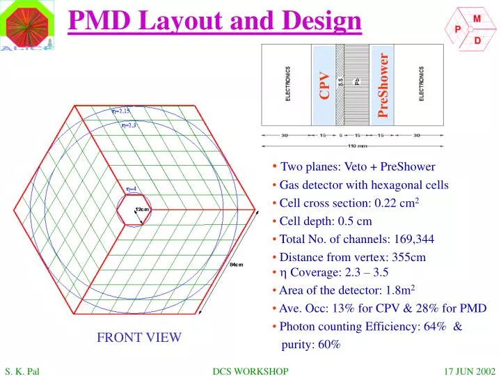
PMD Layout and Design CPV PreShower • Two planes: Veto + PreShower • Gas detector with hexagonal cells • Cell cross section: 0.22 cm2 • Cell depth: 0.5 cm • Total No. of channels: 169,344 • Distance from vertex: 355cm • h Coverage: 2.3 – 3.5 • Area of the detector: 1.8m2 • Ave. Occ: 13% for CPV & 28% for PMD • Photon counting Efficiency: 64% & • purity: 60% FRONT VIEW DCS WORKSHOP
PMD Front-End Electronics FEE Board Mounting and Cooling 4 chip MCM board with MANAS-16 (similar to that of station 3-4-5 of Dimuon Tracking) DCS WORKSHOP
PMD Readout Chambers FEE Gas High Voltage Low Voltage Cooling Flow HV Crate Air Flow LV Crate Temp. PMD Control System The Control System of PMD will consist of following subsystems: 1. High Voltage System 2. Gas System 3. FEE - Low Voltage System - Cooling System DCS WORKSHOP
One Power Supply Line (Current ‘N*I’ in line) ‘N’ Power Supply Lines (Current ‘I’ in each Line) LV PS Distribution Box Read out ~50m FEE FEE FEE FEE Monitoring No. of LV Chains : 180 Voltage : +/- 2.75V, +5V Current : 5A/Chain Model : PL500 from Wiener, 3U size Control ‘On/Off’ CAN Filed Bus Interlock : With cooling Alarms : depending on current limit / channel Schematic of LV Control System DCS WORKSHOP
One Power Supply Line (Current ‘N*I’ in line) ‘N’ Power Supply Lines (Current ‘I’ in each Line) HV PS Distribution Box ~50m SM SM SM SM Monitoring No. of HV Chains : 60 Voltage : - 2000V Current : 100 uA/Channel Model : ISEG or SY1527 Control ‘On/Off’ CAN Filed Bus Interlock : With Gas sub system Alarms : depends on currents/channel Schematic of HV Control System DCS WORKSHOP
PMD Cooling Setup to find out if Air Cooling is adequate for the PMD-FEE. DCS WORKSHOP
Effectiveness of forced air cooling can be seen here. DCS WORKSHOP
Gas Sub System Gas ratio : Ar : Co2 ( Ratio 70: 30) Monitoring : Required Interlock : With HV System Cooling Sub System Control Parameters : - Air flow - Temperature, 60 points wit pt100 Interlock and Alarms : - Interlock with LV Power supply System - Alarms if Temperature is not within limit Alignment : - Few monitoring places DCS WORKSHOP
ALICE PMD DCS WORKSHOP