Download

1 / 22
220 likes | 239 Views
Learn how to use Modbus Poll and Wireshark for Modbus TCP communication with the AKD drive. Includes step-by-step instructions and tips.

E N D
Modbus with the AKDUsing Modbus Poll and WiresharkRev. F Dec. 2, 2011Jimmy Coleman
Reference Sources Modbus Documentation Manual – Modbus section of AKD User Manual and Parameter Table http://www.modbus.org Software Modbus Poll WireShark (for use with Ethernet and Modbus TCP communication) Convert Dec Hex Bin The Lucent Hex Calc 64 Windows Calculator
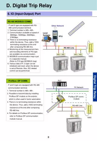
Modbus TCP Communication Settings Port: Modbus communication on the AKD drive is handled through the Service Port. That is the X11 Ethernet port that is use for communication with the Workbench software. Workbench uses ASCII commands over Telnet communication. It is possible to communicate via Modbus and Telnet at the same time from the same PC. TCP/IP: Modbus communication uses the IP address of the drive. The IP address is displayed on the drive after it boots up. It is also displayed on the drive after pressing the B1 button on top of the drive. It can also be read from the Overview screen in Workbench. The AKD uses port 502 for Modbus TCP. There is no CRC code to be added to the Modbus telegram. Data Size: The AKD has memory registers of 16 bit data size. The 32 bit parameters consist of 2 registers and the 64 bit parameters consist of 4 registers. The drive supports Modbus functions 3 (Read Holding Registers) and 16 (Write Multiple Registers). Currently, the AKD supports only reading and writing 2 or 4 registers for one parameter/command at a time. Firmware: Version 1-05-00-000 or later is required for the Modbus features in this document.
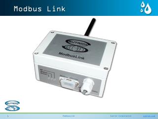
Modbus Poll Software Modbus Poll is a master controller simulator. It can be used to send and receive Modbus communication and record communication traces. Modbus Poll can be downloaded from www.modbustools.com as a trial version. The trial version will automatically disconnect communications every 10 minutes. Communication can be re-established. The purchased license allows for uninterrupted communication.
Starting the Modbus Poll Software Select TCP/IP. Enter the IP address of the AKD drive. Use the default port 502. Save the settings for ease of use next time. The software will open with default setting that are not correct. You will see the error message. Disconnect and click on Connection / Connect… This will open the connection setup window. Or close the Mbpoll1 window and open your saved connection configuration file. Error messages tell you that: - the connection settings are incorrect, - the communication cable is disconnected, - the drive is not functional, - the Read/Write Definition is not correct (see next slide).
Reading Click Setup / Read/Write Definition…, or click the button in the toolbar. Function is “03 Read Holding Registers (4x)”. Slave ID doesn’t matter. Address is the lower 16 bit register number corresponding to the AKD parameter or command. Quantity is 2 for 32 bit parameters and 4 for 64 bit parameters. (Currently the AKD only supports reading/writing one parameter at a time.) The data type is Long Inverse. The checkboxes are for display convenience only.
Example: Read DIN1.MODE Reading the value of DIN1.MODE over Modbus. Look up DIN1.MODE in the parameter table. It is number 122. Actually it is registers 122 and 123, since it is a 32 bit parameter. Set the address to 122 and the Quantity to 2. The data type is always Long Inverse. Modbus Poll send the read request and the drive returns the value of 15. See the Workbench setting of “15 – Quick Stop”.
Example: Read AIN.PSCALE Reading the value of AIN.PSCALE over Modbus. Look up AIN.PSCALE in the parameter table. It is number 8. Actually it is registers 8 through 11, since it is a 64 bit parameter. Set the address to 8 and the Quantity to 4. Set data type to Hex to show all 4 registers. Modbus Poll sends the read request and the drive returns the value. 2AF7FFFC (hex) converts to 720895996 (dec) (If you don’t see this value, it is because the Units Scaling is not set up correctly.) All floating point variables (numbers with three decimal places) are weighted by 1000 in Modbus. So the value is 720.895.996 (with some rounding error due to units scaling).
Writing Click Functions / 16: Write Registers…, or click the button in the toolbar. Function is “16: Write Multiple Registers”. Slave ID doesn’t matter. Address is the lower 16 bit register number corresponding to the AKD parameter or command. Quantity is 2 for 32 bit parameters and 4 for 64 bit parameters. (Currently the AKD only supports reading/writing one parameter at a time.) Use data type Long Inverse for 32 bit parameters and Hex for 64 bit parameters. The data type is set in the Read/Write Definition screen. Double click or click on Edit to change the value. Then click Send to write that value to the drive.
Drive Command Parameters To issue a command, such as DRV.EN, DRV.DIS, HOME.MOVE etc., write a value of 1 to the parameter. Actually, any non-zero value can be written. The action of writing to the parameter is what executes the command. These commands do not have values associated with them, so you can’t read them. If these parameters are read through Modbus, the drive will return a value of zero. When using an HMI, set these command parameters as Write-Only. MT.MOVE is different in that the value written specifies the number of the motion task to be executed. So in this case, the value is important.
Trace – Read 32 bit parameter Click Display / Communication… The Communication Traffic window shows all of the Modbus communication taking place in Modbus Poll. It is in hex. In this example, Modbus Poll was reading DIN.MODE, Modbus address 122 (7Ah). The Tx data “…01 03 00 7A 00 02” defines the read request. 01 is the slave ID, which really doesn’t matter. 03 is the function code for Read. 00 7A is the register number for DIN.MODE (address 122). 00 02 is the number of registers (32 bits) for this parameter. The Rx data “…01 03 04 00 00 00 0F” is the response from the drive. 01 is the slave ID, which really doesn’t matter. 03 is the function code for Read. 04 is the number of bytes of data. 00 00 00 0F is the value of this parameter (0Fh = 15).
Trace – Read 64 bit parameter Click Display / Communication… The Communication Traffic window shows all of the Modbus communication taking place in Modbus Poll. In this example, Modbus Poll was reading AIN.PSCALE, Modbus address 8. The Tx data “…01 03 00 08 00 04” defines the read request. 01 is the slave ID, which really doesn’t matter. 03 is the function code for Read. 00 08 is the register number for AIN.PSCALE (address 8). 00 04 is the number of registers (64 bits) for this parameter. The Rx data “…01 03 08 00 00 00 00 2A F8 00 00” is the response from the drive. 01 is the slave ID, which really doesn’t matter. 03 is the function code for Read. 08 is the number of bytes of data. 00 00 00 00 2A F8 00 00 is the value of this parameter = 720896000 (dec).
Trace – Writing 32 bit parameter Click Display / Communication… In this example, Modbus Poll was reading and writing VL.CMDU, Modbus address 852. Read: The Tx data “…01 03 03 54 00 02” defines the read request. 01 is the slave ID, which really doesn’t matter. 03 is the function code for Read. 03 54 is the register number for VL.CMDU (address 852). 00 02 is the number of registers (32 bits) for this parameter. The Rx data “…01 03 04 00 00 00 00” is the response. 01 is the slave ID, which really doesn’t matter. 03 is the function code for Read. 04 is the number of bytes of data. 00 00 00 00 is the value of this parameter = 0 (dec). Note: There are 6 bytes of data before the Slave ID number. The first 5 bytes can be all zeros when sending a hex string. The 6th byte is the number of bytes to follow, starting with the Slave ID number. Write: The Tx data “…01 10 03 54 00 02 04 00 00 C3 50” is the write. 10 is the function code for Write. 03 54 is the register number for VL.CMDU (address 852). 00 02 is the number of registers 04 is the number of bytes of data. 00 00 C3 50 is the value written to this parameter = 50000 (dec). The Rx data “…01 10 03 54 00 02” is the response. 00 02 is the number of registers written to successfully.
Trace with Wireshark Function Code 03, data size 04 bytes, data = 00 00 07 2F = 1839: AIN.VALUE= 1.839 volts
Wireshark Capturing a Write 10 00 06 00 02 02 00 00 00 14 Function code = 16 Modbus Address = 6 (AIN.OFFSET) Number of 16 bit registers = 2 Data size = 4 bytes Data = 00 00 00 14 = 20 dec: AIN.OFFSET = 0.020 Volts
Working with 64 Bit Numbers Some devices are limited to working with 32 bit variables. Some of the parameters in the AKD are 64 bits. So the data must be sent and received in 32 bit segments. Sign bit: Note that the sign bit is the most significant bit of the upper 32 bits. So the lower 32 bit does not contain a sign bit. Negative numbers require the use of the upper register. Reading a 64 bit variable in two 32 bit segments: Read the upper two registers and the lower two registers separately. Then calculate the 64 bit value by multiplying the upper value by 2^32 and adding to it the lower value. Value = (Upper * 4,294,967,296) + Lower 64 bit to 32 bit re-map: The 64 bit parameters have been remapped to Modbus registers starting at register 2000. These registers use only the lower 31 bits of the parameter plus the sign bit. So it is much easier to work with negative numbers, and allows read/writes of these parameters without any calculations involved.
Dynamic Mapping • Dynamic Mapping is a feature that allow the user to map a particular parameter to a specific Modbus register. • There are two advantages of dynamic mapping: • Communication bandwidth of an HMI can be increased by all of the parameters on a given screen having Modbus register numbers in sequential order. • Dynamic mapping allows mapping only 16 bits of a parameter to one 16 bit register. If less than 16 bits of data are used for a small value, this decreases the amount of data that must be transmitted. • To use dynamic mapping: • Set Modbus register 4096 (0x1000) to 1. • Write the register number you want to map into the register you want to map it to. For AOUT.VSCALE, write a value of 36 to register 8192 and a value of 37 to register 8193. This puts addresses 36 and 37 into registers 8192 and 8193 (32 bits total). • Set register 4096 back to zero. • Now you can read/write registers 8192 and 8193 for AOUT.VSCALE. Do this for any parameters you want to put in sequential registers.
Dynamic Mapping in Workbench Set up dynamic mapping in the Workbench Terminal: MODBUS.DYNMAP enables and disables the dynamic mapping setup mode. 1 = setup mode, 0 = run mode. MODBUS.CLRDYNMAP clears any existing dynamic mapping. MODBUS.ADDR8192 is the parameter containing the value of the fixed 16 bit register that is mapped to the 16 bit register 8192. For each of the dynamic map registers, write the number of the fixed register that you want to map. Example: MODBUS.DYNMAP 1 MODBUS.CLRDYNMAP MODBUS.ADDR8192 856 MODBUS.ADDR8193 857 MODBUS.ADDR8194 2072 MODBUS.ADDR8195 2073 MODBUS.ADDR8196 852 MODBUS.ADDR8197 853 MODBUS.ADDR8198 432 MODBUS.ADDR8199 433 MODBUS.ADDR8200 545 MODBUS.ADDR8201 275 MODBUS.ADDR8202 255 MODBUS.ADDR8203 237 MODBUS.ADDR8204 271 MODBUS.DYNMAP 0 The dynamic mapping settings can be saved to the drive memory and to a parameter file.
Units Scaling Since many devices are limited to 32 bit data size, the AKD firmware supports scaling the 64 bit position parameters to a lower resolution for use through Modbus. Basically, the 32 bit values available in the HMI are broken into a specified number of units per rev and the remaining bits for multi-turn. By default, it is 20 bits per rev and 32-20=12 bits of revs before a roll-over occurs. So the normally 32 bit size position value in the HMI is bit shifted to the right 12 bits. This results in a 20 bit per rev resolution. Three parameters handle this scaling: MODBUS.PSCALE (default = 20, 20 bits per motor rev and 12 bits for counting revs) MODBUS.PIN MODBUS.POUT Set the units to Custom (Custom, Custom/s, and Custom/s^2). Set MODBUS.PIN = 2^MODBUS.PSCALE = 1048576 (for MODBUS.PSCALE=20) Set MODBUS.POUT = UNIT.PIN * 1000 / UNIT.POUT Example: 360 “degrees” per motor rev. All units set to Custom UNIT.PIN = 360 UNIT.POUT = 1 MODBUS.PSCALE = 20 MODBUS.PIN = 1048576 MODBUS.POUT = 360000 (the factor of 1000 is for the floating point decimal (0.000)) Example: 150 “inches” per 29 motor revs. All units set to Custom UNIT.PIN = 150 UNIT.POUT = 29 MODBUS.PSCALE = 20 MODBUS.PIN = 1048576000 MODBUS.POUT = 5172413 (The ratio or 150/29 is not an integer, so there will be rounding error.)