Download
1 / 24
240 likes | 488 Views
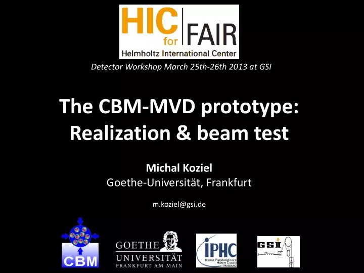
Detector Workshop March 25th-26th 2013 at GSI. The CBM-MVD prototype: Realization & beam test Michal Koziel Goethe-Universität, Frankfurt m.koziel@gsi.de. Outline. CBM experiment and its requirements Prototyping the CBM-MVD Mechanical integration Readout electronics and DAQ

E N D
DetectorWorkshop March 25th-26th 2013 at GSI The CBM-MVD prototype: Realization & beam test Michal Koziel Goethe-Universität, Frankfurt m.koziel@gsi.de
Outline • CBM experiment and its requirements • Prototyping the CBM-MVD • Mechanical integration • Readout electronics and DAQ • Data analysis • Summary and outlook
The MVD – required performances • CBM-MVD will: • improve secondary vertex resolution • background rejection in di-electron measurements • host highly granular silicon pixel sensors featuring fast read-out, excellentspatial resolution and robustness to radiation environment. MVD Up to 4 stations
Research fields towards the MVD Sensor R&D Sensor R&D • IKF infrastructure: • Class 1.000 (ISO 6) clean room • Grey room • Electronic workshop • Mechanical workshop • Equipment: • Manual wire-bonder • Probe station • 3 microscopes • Powerful cooling system • Vacuum chamber Prototype highlights: Mechanical integration • Develop cooling and support with low material budget employing advances materials System integration DAQ • Develop sensor readout system capable to handle high data rates Data analysis
Progress towards the MVD Prototype Demonstrator >2015 Wire bonds 4 sensors ½ (!) of 1st station Flex Cable 200 µm Future MVD: alternated sensors Encapsulation ...will meet all requirements Final 2012 2010 2008 Sensor 50 µm Sensor: MIMOSA-20 ~200 frames/s few 1011neq/cm2 & ~300 kRad 750µm thick Sensor: MIMOSA-26 AHR ~10 kframes/s ~1013 neq/cm2& >300 kRad 50µm thin Sensor: synergy with ALICE (diff. geometry) FEB Readout speed: ~30 kframes/s Al heat sink Radiation tol.: >1013 neq/cm2& >1 Mrad 200 µm Glue Readout Serial/analog Readout CP/digital/high data rates FEB CVDdiamond Cooling & support: pCVD diamond(thermal grade) Cooling & support: TPG+RVC foam Material budget: ~ 2.45 % X0 Material budget: ~ 0.3 % X0
Sensors for the MVD prototype MIMOSA-26 AHR: 0.35 µm process, High Resistivity (HR) EPI (1 kΩ·cm) • Possible issues: • Internal stress -> long-termreliability • Yield after assembly • Sensor pre-selection with probe cards • Main features: • in pixel amplification • binary charge encoding • - discriminatorfor each column • - 0-suppression logic • pitch: 18.4μm • ∼ 0.7 million pixels Bending radius: ~30 cm Size: 21.2 x 10.6 mm2
Aspects addressed during prototyping phase Back scintillator Sensor integration on CVD diamond: Sensor Plane 4 • Adhesive bonding FPC Glue • Positioning DUT Plane 3 Carrier • Wire bonding r/o • Encapsulation T4 • Cooling optimization DUT micro-tracking T3 Double sided sensor integration Micro-tracking • Readout& control • Scalability • Reliability FPC Plane 2 T2 Plane 1 Beam T1 FPC Front scintillator Cooling FPC
Test beam setup at Beam T3 T4 T1 T2 DUT 200 μm CVD diamond 1mm Al Material budget: 0.053 % X0 Material budget: 0.053 % X0 200 μm CVD diamond
Dedicated DAQ sensors based on MIMOSA-26 AHR clock start reset JTAG FPC FPC FPC FEB FEB FEB driver board . . . LVDS, 1m 4x 80 Mbit/s converter board converter board converter board . . . LVDS 4x 80 Mbit/s readout controller board readout controller board Slow control board ~30 m Synergy with HADES readout controller board Hub readout controller board . . . 2 Gbit/s optical fiber to the MVD network General purpose add-on PC HADES TRB V2
Tests before beam time • Stability runs • Slow control cross-check • Tests with radioactive sources • Threshold scans • Cooling check • Test with long cables • ... Laboratory setup Fully operational setup ready for travelling to CERN Corresponding fluence 24 kHz/cm2 (limited by source)
Full beam setup at SPS Beam telescope FEE DAQ Huber cooling system
DAQ performance during beam tests 9 s 40 s CERN-SPS Spill structure 12 sensors running in parallel All sensors are synchronized: No deviations detected within 10 ns precision. • Peak fluence: 350-400 kHz/cm 2 • 20% of MIMOSA-26 computing resources used • Factor of 1000 away from peak fluence @ AuAu 25AGeV ~9 s Limited by beam 110 ms 260 259 Frame number Frame number • DAQ runs very stable:No network errors, no data loss (5 days of tests) • Datarates: 6 MB/s - 25 MB/s but also overload test with +100 MB/s. • JTAG passed also all tests (100 000 programming cycles per chain). • In total 2TB of data stored The Readout Network was proven to be highly scalable.
Data analysis Beam setup 20 – 120 GeVPions CERN SPS North Hall beam • Detection efficiency, Fake Hit Rate, Spatial resolution as a function of threshold voltage (DUT) • 4 inclination angles of 0 ,30 ,45, 60 • Temperature (-6, +6, +17 C) & threshold scans • High beam intensity runs (in average up to 10 hits/frame but due to the non-uniform beam it could also be ~100 hits / some of frames – to be confirmed) DUT Plane 1 Plane 2 Plane 3 Plane 4 Data analysis flow: Cluster analysis 3D alignment Track selection with the 4-plane telescope (straight lines) Response of DUT to charged particles
Cluster shape studies Top 8 most frequently observed cluster shapes 5 7 8 6 3 4 1 2 Cluster classification will be used for further FPGA-based data compression Center of gravity used to compute the “hit” position
Cluster multiplicity studies PRELIMINARY Sensing diode EPI Charge = 80EPIth[μm] / cos [e-]
Detection Efficiency (DUT) PRELIMINARY signal Amplitude noise V threshold probe time NOISE = individual pixel feature V threshold Example: FHR < 10-5 Efficiency > 95% „safe” region
Spatial Resolution (DUT) Spatial resolution: DUT only PRELIMINARY Correlation back - front X (row) back sensor X (row) front sensor FEB • Resultforthe DUT: • σx= 3.3 µm • σY= 3.3 µm Al heat sink π- 200 µm Front sensor FEB Reproducing the intrinsic parameters of the sensors validates the concept of the prototype. Back sensor
Summary • Achieved: • An ultra low material budget (0.3% X0) double-sided micro-tracking device: 2x2 sensors, CVD Diamond, glue & FPC. • Development of tools & assembly procedures. Mechanical integration DAQ • Achieved: • Synchronization • Reliability • Scalability • Slow control & monitoring tools • Data quality • Achieved: • package for alignment and data analysis for test beam setup (telescope-DUT) • online monitoring software (test beam setup) Data analysis
Outlook p. 1 • Towards the CBM-MVD: • Optimizing the digitizer based on data on sensor response • Performance studies of physics cases allowing for more realistic studies on detector performance Data analysis DAQ • Towards the CBM-MVD: • Interface to the CBM DAQ • Optical data link between FEE and DAQ board • Towards the CBM-MVD: • Vacuum compatibility and integration into the CBM-MVD vacuum box • design the MVD platform in the target vacuum chamber • cable routing • finalize services (LV, cooling) • Improve in heat transfer. • Quality assurance while assembling (yields) Mechanical integration
Outlook p. 2 How to move the MVD stations in vacuum ? Mechanical integration • Expertise needed in the future: • Glue: dedicated, radiation tolerant, reworkable, dispensing techniques... • Vacuum:feed-through concepts, MVD stations positioning • Cooling: CO2, or conventional Synergy with FAIR experiment (...and beyond) needed