Download
1 / 76
830 likes | 1.04k Views
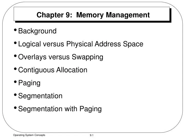
Chapter 9: Memory Management. Background Logical versus Physical Address Space Overlays versus Swapping Contiguous Allocation Paging Segmentation Segmentation with Paging. Background. Program must be brought into memory and placed within a process for it to be executed.

E N D
Chapter 9: Memory Management • Background • Logical versus Physical Address Space • Overlays versus Swapping • Contiguous Allocation • Paging • Segmentation • Segmentation with Paging Operating System Concepts
Background • Program must be brought into memory and placed within a process for it to be executed. • Input queue – collection of processes on the disk that are waiting to be brought into memory for execution. • Select one process from input queue to load it into memory for execution. After execution (terminates) memory space becomes available. • The address space of the computer starts at 00000. • The first address of the user process does not need to be 00000. Operating System Concepts
Compile time Execution time Load time Dynamically loaded system library Other object modules System Library Background • User programs go through several steps before being executed: Source Program Compiler or Assembler Object Module Linkage Editor Load Module Loader In-Memory Binary Memory Image Operating System Concepts
Binding of Instructions and Data to Memory Address binding of instructions and data to memory addresses can happen at three different stages: • Compile time: If memory location known a priori, absolute code can be generated; must recompile code if starting location changes. • Load time: Must generate relocatable code if memory location is not known at compile time. • Execution time: Binding delayed until run time if the process can be moved during its execution from one memory segment to another. Need hardware support for address maps (e.g., base and limit registers). Operating System Concepts
Logical vs. Physical Address Space • The concept of a logical address space that is bound to a separate physicaladdress space is central to proper memory management. • Logical address – generated by the CPU; also referred to as virtual address. • Physical address – address seen by the memory unit. • Logical and physical addresses are the same in compile-time and load-time address-binding schemes; logical (virtual) and physical addresses differ in execution-time address-binding scheme. • The set of all logical address generated by a program. Operating System Concepts
Memory-Management Unit (MMU) • The run-time mapping from virtual to physical addresses is done by the memory-management unit (MMU), which is a hardware device. • The user program deals with logical addresses; it never sees the real physical addresses. • Two different types of addresses: • Logical: range 0 to max. • Physical: range R+0 to R+max; where R is a base value. • The user generates only logical addresses and thinks that the process runs in locations 0 to max. Operating System Concepts
Logical address 345 Physical address 1745 Relocation register Memory 1400 CPU + MMU Memory-Management Unit (MMU) (Cont.) • In MMU scheme, the value in the relocation register is added to every address generated by a user process at the time it is sent to memory. • Example: Dynamic relocation using a relocation register. Operating System Concepts
Overlays • The entire program and data of a process must be in the physical memory for the process to execute. • The size of a process is limited to the size of physical memory. • If a process is larger than the amount of memory, a technique called overlays can be used. • Overlays is to keep in memory only those instructions and data that are needed at any given time. • When other instructions are needed, they are loaded into space that was occupied previously by instructions that are no longer needed. • Overlays are implemented by user, no special support needed from operating system, programming design of overlay structure is complex. Operating System Concepts
Overlays Example • Example: Consider a two-pass assembler. • Pass1 constructs a symbol table. • Pass2 generates machine-language code. • Assume the following: • To load everything at once, we need 200k of memory. Operating System Concepts
Overlays Example (Cont.) • If only 150K is available, we cannot run our process. • Notice that Pass1 and Pass2 do not need to be in memory at same time. • So, we define two overlays: • Overlay A: symbol table, common routines, and Pass1. • Overlay B: symbol table, common routines, and Pass2. • We add overlay driver 10k and start with overlay A in memory. • When finish Pass1, we jump to overlay driver, which reads overlay B into memory overwriting overlay A and transfer control to Pass2. Operating System Concepts
Pass2 (80k) Pass1 (70k) Overlays Example (Cont.) • Overlay A needs 130k and Overlay B needs 140k. Operating System Concepts
Swapping • A process can be swapped temporarily out of memory to a backing store, and then brought back into memory for continued execution. • Backing store – fast disk large enough to accommodate copies of all memory images for all users; must provide direct access to these memory images. • Roll out, roll in – swapping variant used for priority-based scheduling algorithms; lower-priority process is swapped out so higher-priority process can be loaded and executed. • Normally, a process that is swapped out will be swapped back into the same memory space that it occupied previously. • Example: In a multiprogramming environment with Round Robin CPU scheduling, when time slice expires, the memory manager swap out the process that just finished, and swap in another process to the memory space that has been freed. Operating System Concepts
Schematic View of Swapping • Major part of swap time is transfer time; total transfer time is directly proportional to the amount of memory swapped. • The context-switch time in swapping system is high. • Modified versions of swapping are found on many systems, i.e., UNIX and Microsoft Windows. Operating System Concepts
Example 1: Swapping • Let Process P1 size is 100KB and the transfer rate of a hard disk is 1MB/second. • To transfer P1 (100KB) to or from memory takes 100K/1000K per second, which is 1/10 second = 100 milliseconds. • Assume the average latency is 8 milliseconds, then to swap in or out takes 108 milliseconds. The total swap (in and out) is 216 milliseconds for 100KB process. • For efficient CPU utilization, we want our execution time for each process to be long relative to the swap time. • A Round Robin scheduling algorithm, the time slice should be larger than 216 milliseconds (from the above example). Operating System Concepts
0 100K 1MB Contiguous Allocation • Main memory usually is divided into two partitions: • For the resident operating system • For the user processes. Operating System Concepts
0 100K 1MB Example 2: Swapping • A computer system has 1MB of main memory. The O.S. takes 100KB. • Maximum size of user process is 900KB. • User process may be smaller than 900KB. • From previous example if process P1 is 100K the swap time is 108 milliseconds. But, if P1 is 900K then the swap time is 908 milliseconds. • As the size of a process increases the swap time increases too. Main Memory Operating System Concepts
Single – Partition Allocation • Single-partition allocation • Needs Protection. • Protect O.S. code and data from changes by the user processes. • Protect user processes from one another. • We can provide protection by using a relocation-register with a limit register. • Relocation register contains value of smallest physical address. • Limit register contains range of logical addresses. • Each logical address must be less than the limit register. Operating System Concepts
Limit Register Relocation Register Memory Yes CPU < + Physical Address Logical Address No Trap, Address Error Hardware Support for Relocation & Limit Registers Operating System Concepts
Multiple - Partition Allocation • Several user processes residing in memory at the same time. • Memory can be divided into a number of fixed-sized partitions, where each partition may contain exactly one process. Therefore, the degree of multiprogramming is bound by the number of partitions. • Or all memory is available for user processes as one large block (hole). • When a process arrives and needs memory, we search for a hole large enough for this process. • If we find a space, we allocate only as much memory as is needed, keeping the rest available to satisfy future requests. Operating System Concepts
OS OS OS OS process 5 process 5 process 5 process 5 process 9 process 9 process 8 process 10 process 2 process 2 process 2 process 2 Multiple - Partition Allocation (Cont.) • Hole – block of available memory; holes of various size are scattered throughout memory. • Operating system maintains information about:a) allocated partitions b) free partitions (hole) Operating System Concepts
Multiple - Partition Allocation (Cont.) • When no available block of memory (hole) is large enough to hold process, the O.S. waits until a large block is available. • In general, there is at any time a set of holes, of various sizes, scattered throughout memory. • When a process arrives and needs memory, we search this set for a hole that is large enough for this process. • If the hole is too large, it is split into two: • One part is allocated to the arriving process. • The other is returned to the set of holes. • When a process terminates, it releases its block of memory, which is then placed back in the set of holes. • If the new hole is adjacent to other holes, we merge these adjacent holes to form one larger hole. Operating System Concepts
Dynamic Storage-Allocation Problem • First-fit, best-fit, and worst fit are the most common strategies used to select a free hole from the set of available holes. • First-fit: Allocate the first hole that is big enough. Searching starts at the beginning of the set of holes. We can stop searching as soon as we find a free hole that is large enough. • Best-fit: Allocate the smallest hole that is big enough; must search entire list, unless ordered by size. Produces the smallest leftover hole. • Worst-fit: Allocate the largest hole; must also search entire list, unless ordered by size. Produces the largest leftover hole, which may be more useful than the smaller leftover hole from best-fit approach. • First-fit and best-fit better than worst-fit in terms of speed and storage utilization. Operating System Concepts
Fragmentation • External fragmentation – total memory space exists to satisfy a request, but it is not contiguous; storage is fragmented into a large number of small holes. • Example: We have a total external fragmentation of (300+260)=560KB. • If P5 is 500KB, then this space would be large enough to run P5. But the space is not contiguous. • The selection of first-fit versus best-fit can affect the amount of fragmentation. Operating System Concepts
Fragmentation (Cont.) • Internal fragmentation – Memory that is internal to a partition, but is not being used, because it is too small. • Example: Assume next request is for 18462 bytes. • If we allocate exactly the requested block, we are left with a hole of 2 bytes. • The overhead to keep track of this hole will be larger than the hole itself. So, we ignore this small hole (internal fragmentation). Operating System Concepts
Compact Fragmentation (Cont.) • One solution to the problem of external fragmentation is compaction. • The goal is to shuffle memory contents to place all free memory together in one large block. • Example: (Compaction) 3 holes compacted into one large hole 660KB. Operating System Concepts
Fragmentation (Cont.) • The simplest compaction algorithm is to move all processes toward one end of memory; all holes move in the other direction, producing one large hole of available memory. • Example: Comparison of different ways to compact memory. If we use the simple algorithm, we must move P3 and P4 for a total of 600K moved. Operating System Concepts
Fragmentation (Cont.) • Example (Cont.): Or, we can move P4 above P3 moving only 400K. Operating System Concepts
Fragmentation (Cont.) • Example (Cont.): Or, we can move P3 below P4 moving only 200K. Swapping can also be combined with compaction; a process can be swapped out of main memory to a backing store and swapped in again later. Operating System Concepts
Paging • Logical address space of a process can be noncontiguous; process is allocated physical memory whenever the latter is available. • Divide physical memory into fixed-sized blocks called frames (size is power of 2, between 512 bytes and 8192 bytes). • Divide logical memory into blocks of same size called pages. • To run a program of size n pages, need to find n free frames and load program. • When a process is to be executed, its pages are loaded into any available memory frame from the backing store. • The backing store is divided into fixed-sized blocks that are of the same size as the memory frames. Operating System Concepts
Address Translation Scheme • Set up a page table to translate logical to physical addresses. • Address generated by CPU is divided into: • Page number(p) – used as an index into a pagetable which contains base address of each page in physical memory. • Page offset(d) – combined with base address to define the physical memory address that is sent to the memory unit. Operating System Concepts
Address Translation Architecture Operating System Concepts
Paging Example of Logical & Physical Memory Operating System Concepts
Paging Example for a 32-byte Memory with 4-byte each Page • We have 4 pages and each page is 4 bytes. • Logical address 0 is page 0 and offset 0. • Page 0 is in frame 5. • Logical address maps to physical address (5x4)+0=20. • Logical address 3 (page 0, offset 3) maps to physical address (5x4)+3=23. • Logical address 4 (page 1, offset 0) maps to physical address (6x4)+0=24. • Logical address 13 maps to physical address (2x4)+1=9. Page Table Logical Memory Physical Memory Operating System Concepts
Example: Internal Fragmentation in Paging • When we use a paging scheme, we have no external fragmentation, but we may have some internal Fragmentation. • If pages are 2048 bytes, a process of 72,766 bytes would need 35 pages plus 1086 bytes. It would be allocated 36 frames resulting in an internal fragmentation of 2048-1086=962 bytes. • In worst case, a process would need n pages plus one byte. It would be allocated n+1 frames, resulting in an internal fragmentation of almost an entire frame. Operating System Concepts
Example: Free Frames Operating System Concepts
Page Table • In general, each page of the process needs one frame. • If the process requires n pages, there must be at least n frames available in memory. • If there are n frames available, they are allocated to this arriving process. • The first page of the process is loaded into one of the allocated frames, and the frame number is put in the page table for this process. • The next page is loaded into another frame, and its frame number is put into the page table and so on. Operating System Concepts
Frame Table • The operating system is managing physical memory, it must be aware of the allocation details of physical memory: • Which frames are allocated. • Which frames are available. • How many total frames there are and so on. • This information is kept in a data structure called a frame table. • Frame table has one entry for each physical page frame, indicating whether the latter is free or allocated and if it is allocated, to which page of which process or processes. • Clear separation between the user’s view of memory and the actual physical memory. • Paging increases the context-switch time. Operating System Concepts
Structure of the Page Table • Most operating systems allocate a page table for each process. • A pointer to the page table is sorted with other register values (like the instruction counter) in the process control block (PCB). • Page table is kept in main memory. • Page-tablebase register (PTBR) points to the page table. • Page-table length register (PTLR) indicates size of the page table. • Simplest way to implement a page table is as a set of dedicated very high-speed registers for small page table (256 entries). • Most computers allow the page table to be very large. For this machines, the use of fast registers to implement the page table is not feasible. Operating System Concepts
Translation Look-aside Buffers (TLBs) • In this scheme every data/instruction access requires two memory accesses. One for the page table and one for the data/instruction. • The two memory access problem can be solved by the use of a special fast-lookup hardware cache called associative registers or translation look-aside buffers(TLBs). • In TLBs, each register consists of two parts: a key and a value. • When the TLBs are presented with an item, it is compared with all keys simultaneously. • If the item is found, the corresponding value field is output. • The search is fast, but hardware is expensive. • The number of entries in a TLB varies between 8 and 2048. Operating System Concepts
Paging Hardware with TLB Logical address CPU TLB hit Physical address p TLB miss Operating System Concepts
Translation Look-aside Buffers (TLBs) (Cont.) • When a logical address is generated by the CPU, its page number is presented to a set of associate registers (TLB) that contain page numbers and their corresponding frame numbers. • If the page number is found in the TLB, its frame number is immediately available and is used to access memory. • If the page number is not in the TLB, a memory reference to the page table must be made. • We add the page number and frame number to TLB, so that will be found quickly on the next reference. • If the TLB is already full of entries the operating system must select one for replacement. • Every time a new page table is selected the TLB must be flushed (erased) to ensure that next executing process does not use wrong translation information. Operating System Concepts
TLB’s Hit Ratio • The percentage of times that a page number is found in the TLB is called the hit ratio. • An 80-percent hit ratio means that we find the desired page number in the TLB 80 percent of the time. • Example: For 80-percent hit ratio. • If it takes 20 nanoseconds to search TLB and 100 nanoseconds to access memory, then a mapped memory access takes 120 nanoseconds when the page number is in TLB. • If we fail to find the page number in TLB (20 nanoseconds), then we must first access memory for the page table and frame number (100 nanoseconds), then access the desired byte in memory (100 nanoseconds), for a total of 220 nanoseconds. • Effective access time = 0.80x120+0.20x220 = 140 nanoseconds. • In this example, we suffer a 40-percent slowdown in memory access time (from 100 to 140 nanoseconds). Operating System Concepts
TLB’s Hit Ratio (Cont.) • Example: For a 98-percent hit ratio: • Effective access time=0.98x120+0.02x220=122 nanoseconds. • This increased hit ratio produces only a 22-percent slowdown in memory access time. • The hit ratio is clearly related to the number of associative registers (TLBs). • Motorola 68030 processor (used in Apple Macintosh systems) has a 22-entry TLB. • Intel 80486 CPU has 32 registers and claims a 98-percent hit ratio. • In general, number of entries in TLB ranging from 16-512, a hit ratio of 80 to 98 percent can be obtained. Operating System Concepts
Memory Protection • Memory protection implemented by associating protection bits with each frame. • These bits are kept in the page table. • One bit can be define a page to be read and write or read-only. • Every reference to memory goes through the page table to find the correct frame number and at the same time the protection bits can be checked to verify that no writes are being made to a read-only page. • An attempt to write to a read-only page causes a hardware trap to the operating system (memory protection violation). • Valid-invalid bit attached to each entry in the page table: • “valid” indicates that the associated page is in the process’s logical address space, and is thus a legal page. • “invalid” indicates that the page is not in the process’s logical address space. • Illegal addresses are trapped by using valid-invalid bit. • The O.S. sets this bit for each page to allow or disallow accesses to that page. Operating System Concepts
Example: Memory Protection • A system with 14 bit address space (0 to 214 = 16,383). • A program use only addresses 0 to 12,287. • A page size is 2KB (2048). Operating System Concepts
Example: Memory Protection (Cont.) • Addresses in pages 0, 1, 2, 3, 4, and 5 are mapped normally through page table. • Any attempt to generate an address in pages 6 and 7 finds that the valid-invalid bit is set to invalid, and the computer will trap to the operating system (invalid page reference). • Notice that references to page 5 are classified as valid, so accesses to addresses up to 12,287 are valid. • Only addresses from 12,288 to 16,383 are invalid. Operating System Concepts
Multilevel Paging • Most modern computer systems support a very large logical address space. • The page table is very large. • Example: A system with a 32-bit logical address space. • If page size is 4K bytes (212), then a page table may consist of up to 1 million entries (232 / 212) = (220). • Because each entry consists of 4 bytes (32 bits) and we have one million entries, each process may need up to 4 megabytes of physical address space for the page table alone. • A simple solution is to divide the page table into small pieces. • One way is to use a two-level paging scheme (the page table itself is also paged). Operating System Concepts
Two-Level Page-Table Scheme Operating System Concepts
page offset page number pi p2 d 10 10 12 Two-Level Paging Example • A logical address (on 32-bit machine with 4K (212), page size) is divided into: • a page number consisting of (32-12)=20 bits. • a page offset consisting of 12 bits. • Since the page table is paged, the page number is further divided into: • a 10-bit page number. • a 10-bit page offset. • Thus, a logical address is as follows:where p1 is an index into the outer page table, and p2 is the displacement within the page of the outer page table. Operating System Concepts
Address-Translation Scheme • Address-translation scheme for a two-level 32-bit paging architecture. Operating System Concepts