Download

1 / 17
170 likes | 339 Views
Low Voltage Sequential Circuit With a Ring Oscillator Clock. ELEC 6270 Low power design of Electronic Circuits Spring, 2009 Presented by Mridula Allani Under the guidance of Dr. Vishwani Agrawal. Dynamic Voltage and Frequency Scaling. Power Dissipation in electronic circuits.

E N D
Low Voltage Sequential Circuit With a Ring Oscillator Clock ELEC 6270 Low power design of Electronic Circuits Spring, 2009 Presented by Mridula Allani Under the guidance of Dr. Vishwani Agrawal
Dynamic Voltage and Frequency Scaling • Power Dissipation in electronic circuits. • The total power dissipation varies linearly with clock frequency and quadratically with supply voltage. • In idle periods a microprocessor is optimized to run at a low-voltage and less than maximum speed to save power. • Generally, a power management unit controls this operation and reduces the Vdd and fclk after detecting an idle state. • Having an internally generated clock for such designs will decrease the burden on the power-management unit and save clock power .
Globally Asynchronous and Locally Synchronous Architecture Sequential Sequential Asynchronous Protocol Driven Communication Clock Generator Clock Generator • Power dissipation due to clock (appx. 40% of total) can be reduced using such architecture by designing clocks suitable for the local logic blocks.
Project Overview In_reg1 Sequence Generator (Binary Counter) Input Registers sum_out clear In_reg2 Combinational Logic (Ripple Adder) Output Registers count_enable cry_out cry_in ENTITY local_synch IS PORT (set, clear, count_enable: IN STD_LOGIC; cry_out : OUT STD_LOGIC; sum_out: OUT STD_LOGIC_VECTOR( 3 DOWNTO 0 )); END local_synch; ring_clock Clock Distribution Network set Ring Oscillator
Design Considerations • Ripple adder critical path delay = clock period of the ring oscillator. Td = n*(tpHL + tpLH) = 1/fclk tpHL, tpLHrespectively are the fall and rise times of a single inverter Td critical delay of the ripple adder n = number of inverters in a ring oscillator and is odd fclkfrequency of the ring oscillator • Assume the propagation delay for the high-to-low or low-to-high transitions of an inverter to be equal. tpHL + tpLH = 2*Tinv Td = n* 2*Tinv = 1/fclk Tinvis the inverter delay • Delays are calculated as the time between the 50% point of the input waveform and the 50% point of the output waveform.
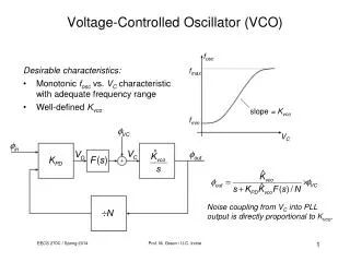
Objectives • Design a ring oscillator clock to meet the critical path delay of the ripple adder. • Observe the variation in clock frequency of the ring oscillator with supply voltage and compare with the theoretical values. • Design a clock distribution network to distribute the clock generated by ring oscillator. • Design a binary counter to supply input vectors to the ripple adder. • Observe the variation of the average and peak powers and the delay of the complete system with supply voltage. • Find the optimum operation condition for the system from the power delay product.
Tools Used • ModelSim SE for behavioral modeling of the blocks. • Leonardo Spectrum for gate-level synthesis. • Design Architect for transistor-level synthesis. • Eldo Spice for voltage, delay, power and critical path delay. • ADK tsmc018 technology file for 0.18 um models.
Experimental Results • Schematic Diagram of the Whole System
Experimental Results Ring Oscillator • Inverter
Experimental Results • From the graph, the optimum operation point is at VDD = 1V.
Theoretical Verification of Dependence of Voltage Scaling on the Frequency of Ring Oscillator (VDD – Vth)α f = k × ─────── VDDα • Variation of frequency with the supply voltage is given by the α-power law, given by • VDD is the supply voltage, Vth is the zero-bias threshold voltage, f is the clock frequency, k and α are constants. • Typical Vth for 0.18 um technology is 0.3932V. • ‘k’ and ‘α’ are calculated from the VDD and f values obtained for 1.8V and 1.6V supply voltage experimentally. • k = 1.097 G and α = 2.74
Comparison of Observed and Calculated Frequencies of Ring Oscillator The experimental results obtained for the remaining voltage 1.4V to 0.2 V in steps of 0.2V are compared to the theoretical results and are tabulated as follows.. • We observe that the calculated frequencies are found to be close to the theoretical results in almost all cases, but do not match the observed frequencies near and below threshold voltages.
Experimental Results Complete System • Ripple Adder
Experimental Results • From the graph, the optimum operation point is at VDD = 1V.
Conclusions • The power-delay product of the ring oscillator was monotonically decreasing, but its energy-delay product had a minimum at 1V supply voltage. • The power-delay product of ripple carry adder is minimum at 1V supply voltage. • Thus, VDD = 1V is the optimum supply voltage. • The whole system could not be simulated due to convergence errors in ELDO.
Future Work • The convergence errors need to be resolved. • This experiment has to be repeated for high leakage technologies and similar trends need to be compared. 16
References • Dr Agrawal’s class slides for ELEC6270, Spring 2009. • Power Management and Dynamic Voltage Scaling: Myths and Facts, David Snowdon, Sergio Ruocco and GernotHeiser • A Deterministic Globally Asynchronous Locally Synchronous Microprocessor Architecture, Matthew Heath and Ian Harris • http://www.wikipedia.org/ 17