Download
1 / 18
260 likes | 605 Views
RF Phase Shifter R&D. March 15, 2005. Proton Driver Review. T. Barrak, B. Foster, I. Gonin, M. Huening, V. Kashikhin, T. Khabiboulinne, A. Makarov, A. Moretti, P. Prieto, J. Santucci, N. Soliak, D. Sun, J. Volk, D. Wildman, and. RF Phase Shifter R&D.

E N D
RF Phase Shifter R&D March 15, 2005 Proton Driver Review T. Barrak, B. Foster, I. Gonin, M. Huening, V. Kashikhin, T. Khabiboulinne, A. Makarov, A. Moretti, P. Prieto, J. Santucci, N. Soliak, D. Sun, J. Volk, D. Wildman, and I. Terechkine
RF Phase Shifter R&D • Concept of phase & amplitude regulation • Performance requirements • Types of phase shifters and known experience • High power test configuration and results • Conclusion I. Terechkine
PD Linac: RF Power Distribution One klystron feeds many cavities. For each cavity, fast change of amplitude and phase of input RF power is required. I. Terechkine
Amplitude and Phase (IQ) Modulator Yttrium Iron Garnet • Ferrite Shifters can be built based on: • Coaxial line, • Strip-line, • Waveguide 1 2 • = (1+2)/2 = (2-1)/2 I. Terechkine
Examples of Phase Shifters Coaxial Device, 1968 L band (1.2 – 1.4 GHz) 350 kW peak power Field Range 800 – 1500 Oe Phase shift - 600° Insertion loss - 0.2 dB Strip-line-based design, AFT for CERN, ~ 2004 352 MHz 250 kW peak power 25%duty cycle 130º phase shift I. Terechkine
Examples of Phase Shifters 805 MHz 500 kW peak power 8% duty cycle 0.15 dB insertion loss Waveguide-based device, Yoon Kang (ANL) for SNS ~ 2000 I. Terechkine
Phase Control Simulations Frequency follows that of the cavity Cavity RF phase close to nominal Detailed simulation (M. Huening, EPAC-2004) shows that 200 sec response time is required. Phase Shifter works hard I. Terechkine
Performance Requirements Frequency: 1300 MHz ± 1 MHz Phase Change: ± 45° RF Power Ratings: 550 kW Peak, 1.5 ms, 10 Hz 550 kW Peak, 4.5 ms, 3.3 Hz Insertion Loss: less than 0.2 dB Response time: time constant ~ 30 s Flange: WR-650 I. Terechkine
Approaching the Problem • Develop and test waveguide-based phase shifter; • Test the coaxial phase shifter available at FNAL • Work with a vendor to build an I/Q modulator I. Terechkine
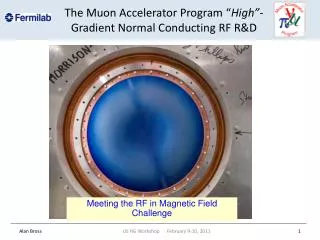
Waveguide Phase Shifter Coil Core • Main design issues: • High power operation • Heat management • Tuning range • Response time I. Terechkine
Phase Shifter Mockup Low Level RF Measurements Results of the low level RF measurements are in a good agreement with modeling (HFSS) I. Terechkine
High Power Test A0 1300 MHz Klystron T = 250 µsec F = 5 Hz Existing A0 interface was used for testing I. Terechkine
High Power Test • Two methods of phase measurements: • Oscilloscope measurements • Using available IQ modulator Available phase zone is limited by sparking that develops near the resonance frequencies SF6 added Max Power - 2000 kW (req. 600 kW) Phase shift - ~ 80° (req. 90° ) I. Terechkine
Further Developments Anti-Parallel Bias Field • Refining RF design • Fast phase shifter prototyping • IQ modulator prototyping Parallel Bias Field I. Terechkine
Coaxial Phase Shifter • Coax design is preferred • at 325MHz • In-house design tested to 660kW at 1300 MHz • Tested at 250 kW at Argonne with APS 352MHz Klystron • Fast coil and flux return should respond in ~50us I. Terechkine
Advanced Ferrite Technology GmbH (AFT) Products: High Power CirculatorsFast Ferrite TunerFast High Power Phase ShifterHybrid Tuner SystemsFerrite MaterialElectrical Power Suppliesfor high power inductive loads The IQ modulator from AFT is expected in May: 1 Magic Tee; 1 straight waveguide section; 2 waveguide - coax transition; 2 FFT´s directly connecting to the transition; 1 control unit for setting phase and amplitude and feedback loop; 1 dual directional coupler for amplitude control; 1 arc detection system. Power supply will be provided by FNAL I. Terechkine
Conclusion • The prototype of a waveguide-based, 1.3 GHz phase shifter shows excellent maximal power and acceptable phase shift performance. • Coaxial phase shifter meets peak power and phase shift requirements both at 1300 MHz and 325 MHz. • Commercial prototype of an I/Q modulator due in spring. • Average power testing, reaction time testing, and IQ modulator modeling should be the next steps of the R&D I. Terechkine
Phase Shifter Development Line • Make low level calibration measurements using “as received” YIG blocks and a large gap dipole magnet • Make steel magnet core and copper waveguide; • Shape YIG block as modeling requires; • Make low level RF measurements; • Make high power measurements; • Investigate ways to improve performance • Make a combination “permanent magnet – high frequency winding” bias magnetic system with ferrite core • Make a waveguide transparent for high frequency magnetic-field • Make low level a.c. measurements to measure response time • Work on a full-scale device design and test DONE Ongoing R&D Engineering I. Terechkine