Download
1 / 24
240 likes | 265 Views
A Tutorial on Battery Simulation - Matching Power Source to Electronic System. Manish Kulkarni and Vishwani D. Agrawal Auburn University Auburn, AL 36849, USA mmk0002@auburn.edu , vagrawal@eng.auburn.edu. Contents. Introduction Powering an electronic system

E N D
A Tutorial on Battery Simulation - MatchingPower Source to Electronic System Manish Kulkarni and Vishwani D. Agrawal Auburn University Auburn, AL 36849, USA mmk0002@auburn.edu, vagrawal@eng.auburn.edu Kulkarni & Agrawal
Contents • Introduction • Powering an electronic system • Statement of the battery problem • Power subsystem, components, characteristics • A Design Example • Circuit simulation for critical path delay and battery current • Battery simulation for lifetime and efficiency • Finding the smallest battery for required system performance • Finding battery for lifetime requirement • Finding minimum energy mode • Summary Kulkarni & Agrawal
Introduction: Powering a System IL RB VB + _ RL VL AHr (capacity) Power supplied to load, PL = IL2 RL = (VB2/RB)(RL/RB) / (1+ RL/RB)2 Ideal lifetime = AHr/IL = AHr.RB (1 + RL/RB) / VB Efficiency = PL / Battery Power = (1+ RB/RL) –1 Kulkarni & Agrawal
Lifetime, Power and Efficiency 1.0 0.8 0.6 0.4 0.2 0.0 10 8 6 4 2 0 Efficiency Lifetime (x AHr.RB /VB) Efficiency or Power PL x VB2/(4RB) Lifetime 0 1 2 3 4 5 6 7 8 RL/RB Kulkarni & Agrawal
Problem Statement Battery problem Solution Determine minimum battery size for efficiency ≥ 85% Increase battery size over the minimum size to meet lifetime requirement. Determine a lower performance mode with maximum lifetime. • Battery should be capable of supplying power (current) for required system performance. • Battery should meet the lifetime (time between replacement or recharge) requirement. • How to extend the lifetime of selected battery. Kulkarni & Agrawal
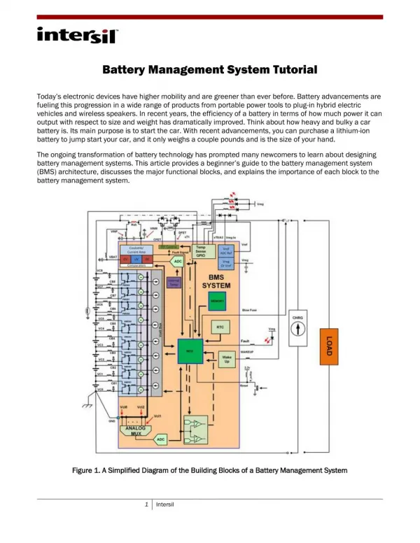
Power Subsystem of an Electronic System Kulkarni & Agrawal
Some Characteristics • Lithium-ion battery • Open circuit voltage: 4.2V, unit cell 400mAHr, for efficiency ≥ 85%, current ≤ 1.2A • Discharged battery voltage ≤ 3.0V • DC-to-DC converter • Supplies VDD to circuit, VDD ≤ 1V for nanometer technologies. • VDD control for energy management. • Decoupling capacitor(s) provide smoothing of time varying current of the circuit. Kulkarni & Agrawal
DC-to-DC Buck (Step-Down) Converter • Components: switch, diode, inductor, capacitor. • Switch control: pulse width modulated (PWM) signal. • Vout= D · Vin, D is duty cycle of PWM control signal. • References: • M. Pedram and Q. Wu, “Design Considerations for Battery-Powered Electronics,” Proc. 36th Design Automation Conference, June 1999, pp. 861–866. • L. Benini, G. Castelli, A. Macii, E. Macii, M. Poncino, and R. Scarsi, “A Discrete-Time Battery Model for High-Level Power Estimation,” Proc. Conference on Design, Automation and Test in Europe, Mar. 2000, pp. 35–41. • Power Supply Circuits, Application Note 2031, Maxim Integrated Products, Oct. 19, 2000, http://pdfserv.maxim-ic.com/en/an/AN2031.pdf Kulkarni & Agrawal
A DC-to-DC Buck Converter Vout Vin PWM control; duty cycle determines Vout Kulkarni & Agrawal
A Design Example • 70 million gate circuit. • Critical path: 32bit ripple-carry adder (RCA) • 352 NAND gates (2 or 3 inputs), 1,472 transistors. • 45nm bulk CMOS technology. • Three-step design procedure: • Circuit characterization – current and delay vs. VDD; find average current for peak performance. • Battery lifetime simulation – minimum battery size for efficiency ≥ 85% at peak performance; battery size for lifetime requirement. • Minimum energy mode – maximum lifetime VDD and clock frequency. Kulkarni & Agrawal
Critical Path Simulation • Simulation model: 45nm bulk CMOS, predictive technology model (PTM), http://ptm.asu.edu/ • Simulator: Synopsys HSPICE, www.synopsys.com/Tools/Verification/AMSVerification/CircuitSimulation/HSPICE/Documents/hspice ds.pdf Kulkarni & Agrawal
Hspice Simulation of 32-Bit RCA, VDD = 0.9V 100 random vectors including critical path vectors Average total current, Icircuit = 74.32μA, Leakage current = 1.108μA Critical path vectors 2ns Kulkarni & Agrawal
Hspice Simulation of 32-Bit RCA, VDD = 0.3V 100 random vectors including critical path vectors Average total current, Icircuit = 0.2563μA, Leakage current = 0.092μA Critical path vectors 200ns Kulkarni & Agrawal
Finding Battery Current, IBatt • Assume 32-bit ripple carry adder (RCA) with about 350 gates represents circuit activity for the entire system. • Total current for 70 million gate circuit, Icircuit = (average current for RCA) x 200,000 • DC-to-DC converter translates VDD to 4.2V battery voltage; assuming 100% conversion efficiency, IBatt = Icircuit x VDD/4.2 • Example: Hspice simulation of RCA: 100 random vectors, VDD = 0.9V, vector period = 2ns, average current = 74.32μA, Ibatt = 3.18A Kulkarni & Agrawal
Delay and Current vs. VDD 3.18A ~ 2ns (500MHz) Kulkarni & Agrawal
Battery Simulation Model Lithium-ion battery, unit cell capacity: N = 1 (400mAHr) Battery sizes, N = 2 (800mAHr), N = 3 (1.2AHr), etc. M. Chen and G. A. Rincón-Mora, “Accurate Electrical Battery Model Capable of Predicting Runtime and I-V Performance,” IEEE Transactions on Energy Conversion, vol. 21, no. 2, pp. 504–511, June 2006. Kulkarni & Agrawal
Lifetime from Battery Simulation 1008s Kulkarni & Agrawal
Finding Battery Efficiency • Consider: • 1.2AHr battery • IBatt = 3.6A • Ideal efficiency = 1.2AHr/3.6A = 1/3 hour (1200s) • Actual lifetime from simulation = 1008s • Efficiency = (Actual lifetime)/(Ideal lifetime) = 1008/1200 = 0.84 or 84% Kulkarni & Agrawal
Battery Efficiency vs. Size Kulkarni & Agrawal
Minimum Battery Size • Consider a performance requirement of 500MHz clock, critical path delay ≤ 2ns. • Circuit simulation gives, VDD = 0.9V and IBatt = 3.18A. • From battery efficiency simulation, for efficiency ≥ 85%, battery capacity should not be less than 1.2AHr, i.e., three-cell (N=3) Li-ion battery. Kulkarni & Agrawal
Battery Lifetime Requirement • Suppose battery lifetime for the system is to be at least one hour. • For smallest battery, size N = 3 (1.2AHr), IBatt = 3.18A, efficiency ≈ 93%, Lifetime = 0.93 x 1.2/3.18 = 0.35 hour • For 1 hour lifetime, battery size N = 3/0.35 = 8.57 ≈ 9. • We should use a 9 cell (3.6AHr) battery. Kulkarni & Agrawal
Minimum Energy Operation • A meaningful measure of the work done by the battery is its lifetime in terms of clock cycles. • For each VDD in the range of valid operation, i.e., VDD = 0.1V to 0.9V, we calculate lifetime using circuit delay and battery efficiency obtained from Hspice simulation. • Minimum energy operation maximizes the lifetime in clock cycles. Kulkarni & Agrawal
Minimum Energy Operation 16 14 12 10 8 6 4 2 0 Battery capacity 3.6AHr Battery capacity 1.2AHr Lifetime (x1012 cycles) 0 0.1 0.2 0.3 0.4 0.5 0.6 0.7 0.8 0.9 1.0 VDD (volts) Kulkarni & Agrawal
Summary seven-times • Battery size should match the current need and satisfy • the lifetime requirement of the system: • (a) Undersize battery has poor efficiency. • (b) Oversize battery is bulky and expensive. • 2 Minimum energy mode can significantly increase battery lifetime. Kulkarni & Agrawal