Download
1 / 41
430 likes | 573 Views
Alternating Current Electricity. NCEA A.S 3.6 Text Chapters 18-19. Why AC?. It can be produced directly from generators It can be controlled by a wide range of components eg resistors,capacitors and inductors. The max voltage can be changed easily using a transformer

E N D
Alternating Current Electricity NCEA A.S 3.6 Text Chapters 18-19
Why AC? • It can be produced directly from generators • It can be controlled by a wide range of components eg resistors,capacitors and inductors. • The max voltage can be changed easily using a transformer • The frequency of the AC can be used for timing
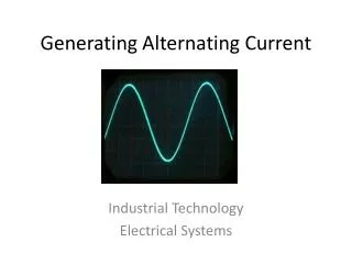
AC Power • P=VxI • Multiplying the graphs gives us a graph where the power is always positive
AC Power • The average voltage in ac is zero since there is an equal amount of positive and negative voltage. • Same for current • The average value of the power used in ac is half that of the peak power
RMS Values • Since voltage and current are always changing we need some way of averaging out their effect. • We use r.m.s values (root-mean-square) • The r.m.s values are the DC values which give the same average power output
AC Voltage DC Voltage (with same power output) Vmax Vrms RMS Values
RMS Values (See text pg 295-296 for derivations of these formulae)
~ AC in Capacitors • In a DC circuit, the current flows until the cap is fully charged and then stops. • In an AC circuit, the current can continue to flow, as the plates become alternately charged positively and negatively
~ Reactance • For both AC and DC circuits, the voltage across the resistor is related to the current by V=IR • A similar relationship exists for a capacitor: • Where Xc is the reactance of the capacitor
Reactance • Reactance is a measure of how a capacitor can limit alternating current • Unit: Ohms • It is similar to resistance but differs in that it is dependent on the frequency of the ac supply. • It also depends on the size of the capacitor.
Reactance • Explanations: Higher f means cap never gets full before current direction changes, so never limits current, so low X Higher C means that it takes more charge to fill it, so never fills before current direction changes, so never limits current, so low X
~ VS VR VC Phase Relationship • In a DC circuit the voltage across components connected in series will add up to the supply voltage • In AC circuits this does not happen • Eg.
Phase Relationship • Reasons: • The meters used to measure the voltage will give rms values, not actual voltages at a point in time • The voltages across the resistor and capacitor are out of phase with each other ie they do not both reach maxs and mins at the same time.
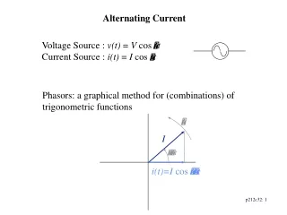
VR I t I VR ω Phase Relationship • The current in the circuit will always be in phase with VR (Reason: because R is constant so bigger V gives bigger I) • This can be shown on a phasor diagram: VR
Phase Relationship • VC will lag 90° behind I (and therefore VR) because the max current flows when the voltage across it’s plates is zero, ie uncharged, and zero current flows when voltage is max ie cap is fully charged • The phasor diagram will look like:
VR VC VR t I I VC ω Phase Relationship • The voltage phasors are not necessarily the same size, but are always 90°out of phase
Vs VC VR ω t VR VS VC RC Circuits • The total voltage in the circuit can be found by adding the VR and VCphasors together
VR=IR R Z VS=IZ XC VC=IXC Impedance • The current is the same everywhere in the circuit so VR and VC are proportional to R and XC • This combination of resistance and reactance which both act to limit the current is called impedance Z
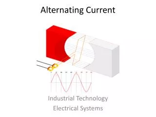
~ AC in Inductors • In a DC circuit an inductor produces an opposing voltage whenever the current changes. • In an AC circuit, the current is always changing so the inductor is always producing an opposing voltage so is always limiting the amount of current that can flow
~ Reactance • For both AC and DC circuits, the voltage across the resistor is related to the current by V=IR • A similar relationship exists for an inductor: • Where XL is the reactance of the inductor
Reactance • It measures how well an inductor can limit alternating current • It depends on the frequency of the ac supply. • It depends on the size of the inductor.
Reactance • Explanations: Higher f means faster rate of change of current, so more back e.m.f, so less current, so higher XL Higher L means more back e.m.f, so less current, so higher XL
Phase Relationship • VL will lead I (and therefore VR) by 90° because the greatest back e.m.f occurs when the current is changing most rapidly, which is when it is passing through zero. When the current has reached it’s max, it is not changing as rapidly so there is no back e.m.f • The phasor diagram will look like:
VR VL VL VR ω t I I Phase Relationship • Again the voltages may be different sizes but will always be 90° out of phase
VS VL VL Vs VR ω VR t LR Circuits • The total voltage in the circuit can be found by adding the VR and VL phasors together
VL=IXL XL VS=IZ Z R VR=IR Impedance • The impedance Z is found by adding R and XL
~ LCR Circuits • This can be an extremely useful circuit set-up, as the current and voltages can change considerably as the frequency is changed
VR VL VS VL Vs ω VR VC VC LCR Circuits • The combined phasor diagram now looks like: t
VL=IXL VS=IZ VL-VC VR=IR VC=IXC Supply Voltage • The supply voltage is now found by adding all 3 phasors together • (VL and VC are combined into one first)
XL Z XL-XC R XC Impedance • The impedance of an LCR circuit is a combination of both the resistance and the reactance. • It is found by adding phasors:
VL VR VS VC Resonance • At low f, VC>VL so VR (and therefore I) is small. • ie. Capacitors limit the current better at low frequencies
VL VS VR VC Resonance • At high f, VL>VC so VR (and therefore I) is small. • ie. Inductors limit the current better at high frequencies
VL VS VR VC Resonance • At resonance, VL=VC and they cancel each other out. So VS=VR and if VR is at max then I is at max.
Resonance • At resonance, a circuit has the maximum possible current for a given supply voltage VS. • At resonance:
Resonant Frequency • A circuit will have a resonant frequency f0 which depends on L and C:
t Rectifying AC • Rectifying – turning AC into DC • Putting a diode into the circuit will do this:
t Rectifying AC • A bridge rectifier will do this:
12V AC out 240V AC in 12V DC (smoothing cap) Rectifying AC • A bridge rectifier circuit looks like this:
t Rectifying AC • A bridge rectifier with a capacitor in parallel with it will do this: (the bigger the cap the smoother the DC)