Download
1 / 39
390 likes | 545 Views
The new vacuum mode separator at Jyväskylä J. Uusitalo, J. Sarén, M. Leino RITU and γ-groups University of Jyväskylä, Department of Physics UK, Daresbury, Liverpool, Manchester, York. JUROGAM RITU GREAT TDR. IReS target chamber. Köln plunger. SACRED. LISA University of Liverpool

E N D
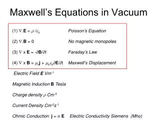
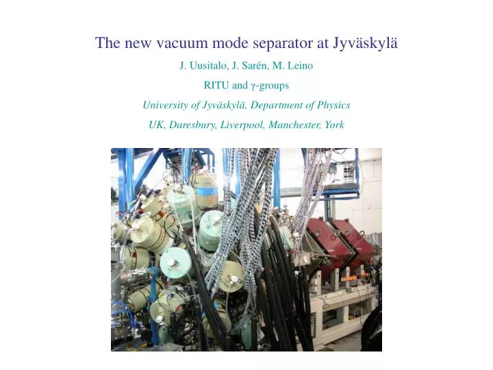
The new vacuum mode separator at Jyväskylä J. Uusitalo, J. Sarén, M. Leino RITU and γ-groups University of Jyväskylä, Department of Physics UK, Daresbury, Liverpool, Manchester, York
JUROGAM RITU GREAT TDR IReS target chamber Köln plunger SACRED LISA University of Liverpool SAGE
Separator plan for Bratislava (A. P. Popeko) Configuration – QQQEDMD Central trajectory length 5.62 m Quadrupoles: eff. length 35 cm, full aperture 10 cm Magnetic dipole: rad. of bend 1 m, defl. angle 35 deg., gap 10 cm, max. field 1 T Electric dipole: rad. of bend 4 m, defl. angle 10 deg., gap 12 cm, max. field ± 150 kV
Bratislava separator Angular focus in x- and y-directions Energy focus and mass dispersion in x-direction
Charged particle in electric and magnetic fields • Magnetic rigidity: • Electric rigidity: • Resolving power: • Deflection angles in electric field: • Universal features: • - Both electric and dipole fields are needed • - Beam is dumped inside the first dipole (chamber) • Mass resolving power about 350 FWHM can be reached • (with 2 mm beam spot size) • - Full energy beam suppression factor of 109-1015 can be expected
Mass separators all around the world: some trends DRS: Q1-Q2-Q3-WF1-WF2-Q4-Q5- Q6-S1-S2-MD1-Q7-Q8-Q9 (13.0 m) CARP: Q1-MD1-H1-H2-ED1-H3-Q2 CAMEL: Q1-Q2-ED1-S1-MD1-S2-ED2 HIRA: Q1-Q2-ED1-M1-MD1-ED2-Q3-Q4 (8.6 m) JAERI-RMS: Q1-Q2-ED1-MD1-ED2-Q3-Q4-O1 (9.4 m) FMA: Q1-Q2-ED1-MD1-ED2-Q3-Q4 (8.2 m) EMMA: Q1-Q2-ED1-MD1-ED2-Q3-Q4 (9.04 m) JYFL new: Q1-Q2-Q3-ED1-MD1 (6.84 m) Q quadrupole S sextupole H hexapole M multipole O octupole WF velocity filter ED electric dipole MD magnetic dipole
Design principles and aberrations - Maximizing angular, mass and energy acceptance while minimizing geometric and chromatic aberrations. - The largest aberrations are (x|δ2), (x|θδ) and (x|θ2). These are minimized by adding a curvature to the magnetic dipole entrance and exit. - Higher order aberrations found to be negligible.
Optical layout in floor coordinates Reference particle: A = 100, Q = 26, E = 100 MeV
Angular focus in x- and y-directions X-direction, 5 angles: 0, ±15 and ±30 mrad Y-direction, 5 angles: 0, ±20 and ±40 mrad
Energy focus and mass dispersion in x-direction Energy deviation: 0, ±3.5 and 7.0 % 3 different angles 3 different energies 3 different masses Angles: 0 and ±30 mrad, Masses: 100 and ± 1 % Energies: 100 and ± 7.0 %
Main properties of the new JYFL separator compared to EMMA @ TRIUMF EMMA JYFL new Length from target to focal plane (m) 9.04 6.84 ---------------------------------------------------------------------------------------------------------------------------------------- Dipoles MD ED1, ED2 MD ED ---------------------------------------------------------------------------------------------------------------------------------------- Radius of curvature (m) 1.0 5.0 1.0 4.0 Deflection angle (o) 40 20 40 20 Effective field boundary inclination angles (o) 8.3 0 8.0 0 Effective field boundary radii (m) 3.472 - 2.800 - Gap (cm) 12 12.5 10 14 Maximum field 1.0 T 50 kV/cm 1.0 T 42 kV/cm Maximum rigidity 1.0 Tm 25 MV 1.0 Tm 17 MV ---------------------------------------------------------------------------------------------------------------------------------------- Magnetic lenses Q1 Q2, Q3 Q4 Q1 Q2, Q3 ---------------------------------------------------------------------------------------------------------------------------------------- Bore diameter (cm) 7 15 20 10 15 Effective length (cm) 14 30 40 25 35 Maximum pole tip field (T) 1.21 0.87 0.81 0.5 0.75 Maximum field gradient (T/m) 35 12 8.1 10 10
Main properties of the new JYFL separator compared to FMA @ ANL FMA JYFL new Length from target to focal plane (m) 8.20 6.84 ---------------------------------------------------------------------------------------------------------------------------------------- Dipoles MD ED1, ED2 MD ED ---------------------------------------------------------------------------------------------------------------------------------------- Radius of curvature (m) 1.0 4.0 1.0 4.0 Deflection angle (o) 40 20 40 20 Effective field boundary inclination angles (o) 7.0 0 8.0 0 Effective field boundary radii (m) 2.8 - 2.8 - Gap (cm) 12 10 10 14 Maximum field 1.1 T 50 kV/cm 1.0 T 42 kV/cm Maximum rigidity 1.1 Tm 20 MV 1.0 Tm 17 MV ---------------------------------------------------------------------------------------------------------------------------------------- Magnetic lenses Q1 Q2 Q3, Q4 Q1 Q2, Q3 ---------------------------------------------------------------------------------------------------------------------------------------- Bore diameter (cm) 10 10 20 10 15 Effective length (cm) 30 20 30 25 35 Maximum pole tip field (T) 0.8 0.8 0.8 0.5 0.75 Maximum field gradient (T/m) 16 16 10.7 10 10
Main properties of the new JYFL separator compared to EMMA @ TRIUMF • EMMAJYFL new • - Configuration QQEDMDEDQQ QQQEDMD • Horizontal magnification -2.08 -1.55 • Vertical magnification 1.33 -4.48 • - M/Q dispersion 10.0 mm/% (variable) 8.1 mm/% • - First order resolving power, 240 259 • 2 mm beam spot • Solid angle acceptance 16 msr 10 msr • central m/q and energy • - Energy acceptance for • central mass and angle +25 % - 17 % +20 % - 15 % • - M/Q acceptance 4 % 7 %
Main properties of the new JYFL separator compared to FMA @ ANL • FMAJYFL new • - Configuration QQEDMDEDQQ QQQEDMD • Horizontal magnification -1.93 -1.55 • Vertical magnification 0.98 -4.48 • - M/Q dispersion 10.0 mm/% (variable) 8.1 mm/% • - First order resolving power, 259 259 • 2 mm beam spot • Solid angle acceptance 8 msr 10 msr • central m/q and energy • - Energy acceptance for • central mass and angle +20 % - 15 % +20 % - 15 % • - M/Q acceptance 4 % 7 %
Properties of the new JYFL separator compared to the planned Bratislava separator • BratislavaJYFL new • - Configuration QQQEDMD QQQEDMD • - Horizontal magnification -1.0 -1.56 • - Vertical magnification -4.42 -4.48 • - M/Q dispersion 6.0 mm/% 8.1 mm/% • - First order resolving power, 300 259 • 2 mm beam spot • Solid angle acceptance 3.6 msr 10 msr • central m/q and energy • - Energy acceptance for • central mass and angle +25 % - 20 % +20 % - 15 % • M/Q acceptance 4 % 7 % • TOF needed to obtain • mass res. power
What kind of research work can be done were RITU separator is not feasible Probing the N Z line up to 112Ba - decay spectroscopy (proton and -particle decay) at the 100Sn region - proton drip-line spectroscopy o competition between proton and gamma decay o new proton emitters - rp-process o masses, half-lives and isomers in N=Z nuclei determine the rp- process synthesis rate - proton-neutron pairing interaction with T = 0 and T = 1 - mirror nuclei o effects of increasing Coulomb field o study of isospin symmetry breaking o proton skins (N < Z nuclei) - super-deformation and hyper-deformation (N Z 40)
Methods - focal plane detector system: o DSSSD and PSAC (1 mm granularity) - Tracking o PSAC and IC - A and Z- identification o tape system o planar-Ge and clover Ge - focal plane spectroscopy - , proton, , , -delayed protons and alphas - prompt and delayed coincidences - in-beam spectroscopy tagging with focal plane measures - Recoil beta tagging (RBT), betas, beta-delayed protons - Recoil decay tagging (RDT), protons, alphas - Recoil delayed gamma tagging
JIonO – IonOptical simulations, Jan Sarén • Features (some are not implemented yet): • both graphical and text interfaces • uses GICO/GIOS transfer matrices • adjustable aperture slits • export/import data • real particle parameters as input data (m, E, q) • Multiple types of plots • Windows and Linux
X-deviations versus TOF can be seen in phase space corrected data -> time correction can be made to improve x-resolution
Bratislava separator TOF (1 m) vs focal plane position. Masses 99, 100, 101 with charge states 25, 26, 27 Energy 100(7) MeV σx = ± 30 mrad, σy = ± 30 mrad
Simulation of electric field in deflector (code Poisson Superfish) • gap 14 cm • rounded edges • splitted anode • maximum • voltage • between plates • is about 0.6 MV • 3-dim. analysis • under work • (COMSOL • multiphysics)
Simulating particle trajectories in deflector field Simple modified Euler equation is used to trace particles in electric field. 147Tm: 222 MeV, 147 u, 37 e Real transfer matrix coefficients can be obtained from these simulations. This more realistic matrix can be used in optical simulations of the new separator. 92Mo: 362 MeV, 92 u, 32 e 100 MeV, 100 u, 26 e 200 MeV, 50 u, 21 e
40Ca + 40Ca → 80Zr* → 78Zr + 2n Elab = 110 MeV (MOT) Target 400 μg/cm2 M = 78, Q = 18, 19, 20, E = 46(6) MeV, (2n, pn, 2p), 15 % M = 77, Q = 18, 19, 20, E = 46(6) MeV, (3p, 2pn), 72 % M = 75, Q = 17, 18, 19, E = 44(6) MeV, (αn), 3 % M = 74, Q = 17, 18, 19, E = 44(6) MeV, (α2n), 10 % σx,y = ± 35 mrad
48Ca + 208Pb → 256No* → 254No + 2n Elab = 215 MeV (MOT) Target 400 μg/cm2 M = 254, Q = 17, 18, 19, E = 35(5) MeV, σx,y = ± 50 mrad
High acceptance mode Quadrupole polarities inversed solid angle acceptance 10 msr → 14 msr 1st order resolving power 259 → 155
d(132Sn,p)133Sn @ 6 MeV/n 100 μg/cm2 (CD2)n target Beam energy spread ± 0.17 % Recoil energy spread ± 0.23 % (± 2.5 %) In coincidence with protons emitted between 120o and 180o in the lab Rigidities too high 8.8 μm Au foil to slow down the products → angular spread σ = 22 mrad, Energy spread less than 1 % Final input: Uniform distributions Beam spot size x,y = ± 0.5 mm Beam: E = 325(3) MeV, σx = ± 35 mrad, σy = ± 52 mrad Recoils: E = 322(3) MeV, σx = ± 35 mrad, σy = ± 52 mrad
EMMA versus JYFL new Input: x, y: ± 1.5 mm x´, y´: ± 20 mrad Energy is as they come from reactions colors coded as: blue: 132Sn beam red: 133Sn (all fragment angles) green: 133Sn (coincidence with fragment lab. angles 120 – 180 deg.) magenta: 133Sb fusion product light blue: 133Sb via d,n transfer
EMMA versus JYFL new Input: x, y: ± 1.5 mm x´, y´: ± 20 mrad Energy is as they come from reactions colors coded as: blue: 132Sn beam red: 133Sn (all fragment angles) green: 133Sn (coincidence with fragment lab. angles 120 – 180 deg.) magenta: 133Sb fusion product light blue: 133Sb via d,n transfer
EMMA versus JYFL new Input: x, y: ± 1.5 mm x´, y´: ± 20 mrad Energy is as they come from reactions colors coded as: blue: 132Sn beam red: 133Sn (all fragment angles) green: 133Sn (coincidence with fragment lab. angles 120 – 180 deg.) magenta: 133Sb fusion product light blue: 133Sb via d,n transfer
54Fe + 58Ni → 112Xe → 110Xe + 2n @ 195 MeV, B. Cederwall et. al., Comparison between the gas-filled recoil separator RITU and the new vacuum mode separator With 5 pnA 54Fe beam the rates using the gas-filled recoil separator RITU are: JUROGAM ~ 100 kHz Focal plane silicon rate ~ 5 kHz using the vacuum-mode separator are: JUROGAM ~ 100 kHz - about 50 % less transmission, 3 charge states Focal plane silicon rate ~ 2.5 kHz - using mass slits, 3 charge states and mass 110 (106) Focal plane silicon rate ~ 1.0 kHz → 20 pnA beam will give JUROGAM ~ 400 kHz Focal plane silicon rate ~ 4.0 kHz and 100 % more yield for 110Xe when compared to RITU Should be valid for all cases for A < 110 if correlation technique is needed for final identification and/or tagging Weak evaporation channels 2n, 3n, ... pn, p2n…