Download
1 / 30
420 likes | 1.09k Views
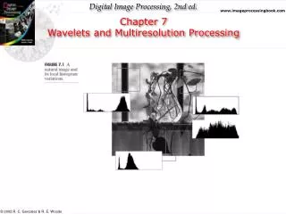
Digital Image Processing. Wavelets and Multiresolution Processing (Background). Christophoros Nikou cnikou@cs.uoi.gr. Wavelets and Multiresolution Processing. All this time, the guard was looking at her, first through a telescope, then through a microscope, and then through an opera glass.

E N D
Digital Image Processing Wavelets and Multiresolution Processing(Background) Christophoros Nikou cnikou@cs.uoi.gr
Wavelets and Multiresolution Processing All this time, the guard was looking at her, first through a telescope, then through a microscope, and then through an opera glass. Lewis Carrol, Through the Looking Glass
Contents • Image pyramids • Subband coding • The Haar transform • Multiresolution analysis • Series expansion • Scaling functions • Wavelet functions • Wavelet series • Discrete wavelet transform (DWT) • Fast wavelet transform (FWT) • Wavelet packets
Introduction Unlike the Fourier transform, which decomposes a signal to a sum of sinusoids, the wavelet transform decomposes a signal (image) to small waves of varying frequency and limited duration. The advantage is that we also know when (where) the frequency appear. Many applications in image compression, transmission, and analysis. We will examine wavelets from a multiresolution point of view and begin with an overview of imaging techniques involved in multiresolution theory.
Introduction (cont...) Small objects are viewed at high resolutions. Large objects require only a coarse resolution. Images have locally varying statistics resulting in combinations of edges, abrupt features and homogeneous regions.
Image Pyramids Originally devised for machine vision and image compression. It is a collection of images at decreasing resolution levels. Base level is of size 2Jx2J or NxN. Level j is of size 2jx2j.
Image Pyramids (cont…) Approximation pyramid: At each reduced resolution level we have a filtered and downsampled image.
Image Pyramids (cont…) Prediction pyramid: A prediction of each high resolution level is obtained by upsampling (inserting zeros) the previous low resolution level (prediction pyramid) and interpolation (filtering).
Image Pyramids (cont…) Prediction residual pyramid: At each resolution level, the prediction error is retained along with the lowest resolution level image. The original image may be reconstructed from this information.
Image Pyramids (cont…) Approximation pyramid Prediction residual pyramid
Subband Coding An image is decomposed to a set of bandlimited components (subbands). The decomposition is carried by filtering and downsampling. If the filters are properly selected the image may be reconstructed without error by filtering and upsampling.
Subband Coding (cont…) A two-band subband coding Approximation filter (low pass) Detail filter (high pass)
Subband Coding (cont…) The goal of subband coding is to select the analysis and synthesis filters in order to have perfect reconstruction of the signal. It may be shown that the synthesis filters should be modulated versions of the analysis filters with one (and only one) synthesis filter being sign reversed of an analysis filter.
Subband Coding (cont…) The analysis and synthesis filters should be related in one of the two ways: These filters are called cross-modulated.
Subband Coding (cont…) Also, the filters should be biorthogonal: Of special interest in subband coding are filters that move beyond biorthogonality and require to be orthonormal: In addition, orthonormal filters satisfy the following conditions: where the subscript means that the size of the filter should be even.
Subband Coding (cont…) Synthesis filters are related by order reversal and modulation. Analysis filters are both order reversed versions of the synthesis filters. An orthonormal filter bank may be constructed around the impulse response of g0 which is called the prototype. 1-D orthonormal filters may be used as 2-D separable filters for subband image coding.
Subband Coding (cont…) Approximation subband Vertical subband Horizontal subband Diagonal subband
Subband Coding (cont…) The subbbands may be subsequently split into smaller subbands. Image synthesis is obtained by reversing the procedure.
Subband Coding (cont…) The wavy lines are due to aliasing of the barely discernable window screen. Despite the aliasing, the image may be perfectly reconstructed.
The Haar Transform It is due to Alfred Haar [1910]. Its basis functions are the simplest known orthonormal wavelets. The Haar transform is both separable and symmetric: T=HFH, F is a NxN image and H is the NxN transformation matrix and Tis the NxN transformed image. Matrix H contains the Haar basis functions.
The Haar Transform (cont…) • The Haar basis functions hk(z) are defined for in 0≤ z ≤1, for k=0,1,…, N-1, where N=2n. • To generate H: • we define the integer k=2p+q-1, with 0≤ p ≤N-1. • if p=0, then q=0 or q=1. • if p≠0, 1≤q ≤2p • For the above pairs of p and q, a value for k is determined and the Haar basis functions are computed.
The Haar Transform (cont…) The ith row of a NxN Haar transformation matrix contains the elements of hk(z) for z=0/N, 1/N, 2/N,…, (N-1)/N.
The Haar Transform (cont…) For instance, for N=4, p,q and k have the following values: and the 4x4 transformation matrix is:
The Haar Transform (cont…) Similarly, for N=2, the 2x2 transformation matrix is: The rows of H2 are the simplest filters of length 2 that may be used as analysis filters h0(n) andh1(n) of a perfect reconstruction filter bank. Moreover, they can be used as scaling and wavelet vectors (defined in what follows) of the simplest and oldest wavelet transform.
An introductory example to wavelet analysis • Combination of the key features examined so far: • pyramids, • subband coding, • the Haar transform. • The decomposition is called the discrete wavelet transform and it will be developed later in the course.
An introductory example to wavelet analysis (cont…) With the exception of the upper left image, the histograms are very similar with values close to zero. This fact may be exploited for compression purposes. The subimages may be used to construct coarse and fine resolution approximations.
An introductory example to wavelet analysis (cont…) The decomposition was obtained by subband coding in 2-D. After the generation of the four subbands, the approximation subband was further decomposed into four new subbands (using the same filter bank). The procedure was repeated for the new approximation subband. This procedure characterizes the wavelet transform as the subimages become smaller in size.
An introductory example to wavelet analysis (cont…) This is not the Haar transform of the image. The Haar transform of the image is different. Although these filter bank coefficients were taken by the Haar transformation matrix, there is a variety of orthonormal filters that may be used.
An introductory example to wavelet analysis (cont…) Each subimage represents a specific band of spatial frequencies in the original image. Many of the subimages demonstrate directional sensitivity (e.g. the subimage in the upper right corner captures horizontal edge information in the original image).