Download
1 / 24

E N D
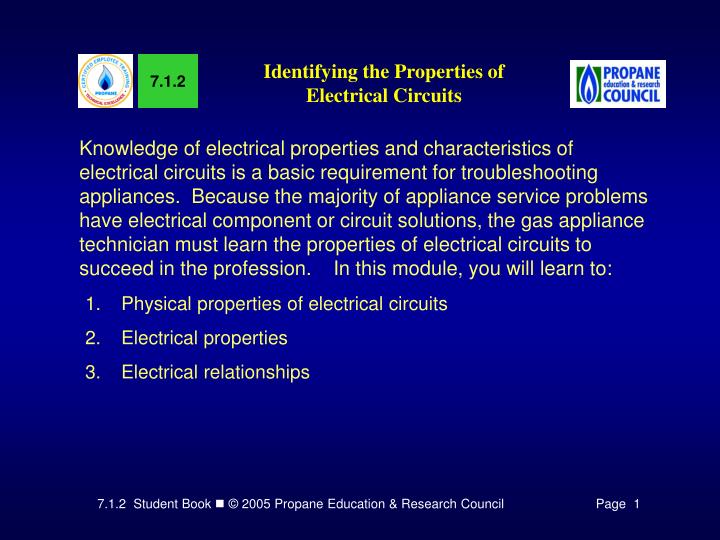
7.1.2 Identifying the Properties of Electrical Circuits Knowledge of electrical properties and characteristics of electrical circuits is a basic requirement for troubleshooting appliances. Because the majority of appliance service problems have electrical component or circuit solutions, the gas appliance technician must learn the properties of electrical circuits to succeed in the profession. In this module, you will learn to: • Physical properties of electrical circuits • Electrical properties • Electrical relationships
Identifying the physical properties of electrical circuits A close examination of a simple electrical circuit will show the circuit consists of four circuit elements as follows: • Source of power • Control switch or switches • Load device • Interconnecting wires
Figure 1 illustrates the four elements of a flashlight electrical circuit drawn in pictorial form to show a picture of the circuit elements. • (a) Source of power. Batteries are used as a source of power. • Control switch. A control switch is used to connect or disconnect the power source from the load. • Load device. The load device in the flashlight circuit is the lamp bulb. • Interconnecting wires. In place of interconnecting wires the metal flashlight case and spring are used to complete the circuit.
Figure 2. Light De-energized Switch Open - Path Open Figure 3.Switch Closed - Path ClosedLight Energized
Figure 4.Switch Open - Path OpenLight De-energized Figure 5.Switch Closed - Path ClosedLight Energized
A control circuit is typically used in appliances to as a switch to turn the flow of electricity on and off to load devices in other circuits.A fuse (5) is added to the circuit to limit the current flowing in the circuit. Figure 6.Control Circuit Figure 7.Connector Diagram of a Flashlight
Identifying electrical properties There are basically three electrical quantities present in all operating electrical circuit/systems. When performing a troubleshooting procedure, the technician's job is to check for the presence of these quantities and determine if they are in the correct relationships. The quantities are: • Electrical current that flows in the circuit(s) • Source voltage applied to the circuit/system • Electrical resistance to the current flowing in the circuit/system
Electrical current flowing in an electrical circuit/system may be compared to the flow of propane through a piping system. However, there is one primary difference: In a propane piping system the propane flows from the source, (storage container) to the load, (burner) where it is consumed. In an electrical circuit/system the current flows from the voltage source, (battery) through the load, (lamp) and back to the voltage source. Figure 9. Comparing Propane Flow with Electrical Current Flow
Electrical current may be referred to as electrons moving in the conductor. Just as the rate of flow of propane moving through a piping system is measured in cubic feet, the rate of flow of electrons moving through an electrical conductor is measured in amperes. The mathematical symbol for amperes is the letter "I" or "A." An ammeter is used to measure the amperes of electricity flowing in a circuit.
Source voltage. The source voltage in the flashlight circuit is produced by two batteries. However, a voltage source is any device which uses some kind of energy such as mechanical, chemical, heat, etc. to produce electricity. Voltage producing devices commonly used include: • Electrical generators (mechanical energy) • Batteries (chemical energy) • Thermocouples (heat) Voltage is a term used as a measure of electromotive force. Electromotive force is the amount of electrical pressure difference between points in an electrical circuit. It is this pressure difference which forces electrical current to flow in a circuit. The pressure in an electrical circuit is measured in volts. Volts may be compared to pounds or inches water column (W.C.) as measures of pressure in a propane supply line.
The amount of voltage (electrical pressure) in an electrical circuit is measured with a voltmeter. This may be compared to the amount of propane pressure in a propane supply being measured with a gauge or a manometer. The mathematical symbol for volts is "E" or "V". Electrical resistance is the opposition to the flow of electrical current (electron flow) in an electrical circuit. The resistance in an electrical circuit/system is determined by the size of the electrical conductor and resistive load devices in the circuit(s). Electrical resistance may be compared to the opposition to the flow of propane through a piping system caused by friction on the pipe walls, pipe fittings, valves, regulators, etc. Electrical resistance is measured in ohms. The mathematical symbol for electrical resistance is the letter "R." The Greek symbol may be used for ohms.
Electrical power. The unit of power most commonly used in the electrical industry is the watt. Energy charges in the electrical industry are based on watt hours. This compares to the Btu's per hour used in the propane industry. One watt hour of power is equal to 3,413 BTU's per hour. The mathematical symbol for electrical power is the letter "W."
Identifying electrical relationships Ohm’s law. The mathematical formula used to describe the relationships among the voltage, current, and resistance in an electrical circuit is known as Ohm's law. The amount of current which flows in a circuit is directly proportional to the applied voltage. In other words, when voltage increases, the current increases; and when the voltage decreases the current decreases. If the voltage remains constant, the current will change as the resistance changes, but in the opposite direction. The current will decrease as the resistance increases and will increase as the resistance decreases. Ohm's law states: The current which flows in a circuit (I) is directly proportional to the applied voltage (E) and inversely proportional to the resistance (R).
volts = amps x ohms amps = volts / ohms ohms = volts / amps Figure 10. Ohm's Law in a Mathematical Equation There are three ways of stating this fundamental law: (a) The pressure in volts is equal to the current in amperes multiplied by the resistance in ohms: E = I x R (volts = amps times ohms). (b) The current in amperes is equal to the pressure in volts divided by the resistance in ohms: (amps = volts divided by ohms). (c) The resistance in ohms is equal to the pressure in volts divided by the current in amperes: (ohms = volts divided by amps).
Figure 11. Ohm's Law Applied to a Flashlight Electrical Circuit
Figure 12. Ohm's Law Applied to a Flashlight Electrical Circuit
Figure 13. Ohm's Law Applied to a Flashlight Electrical Circuit
watts = amps x volts volts = watts / amps amps = watts / volts Figure 14. Watt's Law in a Mathematical Equation Watt’s law. Electrical power is the rate at which energy is expended by (or supplied to) an electrical circuit. Electrical power is expressed in watts. The equation P=E X I states the power expended (or supplied) to an electrical circuit is equal to the voltage (E) in volts multiplied by the electrical current (I) in amperes.
Time to See If You Got the Key Points of This Module… • Complete the Review on pages 11 - 13. • See if you are ready for the Certification Exam by checking off the performance criteria on page 14.