Download

1 / 25
250 likes | 386 Views
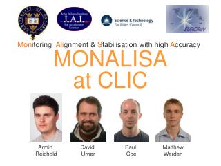
Welcome to MONALISA. A brief introduction. Who we are. Armin Reichold. David Urner. Paul Coe. Matthew Warden. Electronics support from CEG C entral E lectronics G roup. ...also collaborate closely with the LiCAS project. The context of our work.

E N D
Welcome to MONALISA A brief introduction
Who we are... Armin Reichold David Urner Paul Coe Matthew Warden Electronics support from CEG Central Electronics Group ...also collaborate closely with the LiCAS project
The context of our work • HEPHigh Energy (particle) Physics • Linear accelerators • Need for alignment monitoring • ATF-2 Advanced Test Facility • An envisaged monitor system • Five summer projects
High Energy "Frontier" • To "boldly" accelerate particles in large numbers • Nature does this already: accelerated particles strike the earth continuously as cosmic rays • but the results are hard to monitor • there's no control over the particles Collaborations of physicists build: • accelerators to collide beams and • detectors to monitor the results
Exploring natures spectrum • Particle on particle centre of mass energy is the spectral variable. • Collisions between beams excite resonances • Particles are created • The resulting debris is • detected • filtered and • recorded for analysis
Linear accelerators • Bunches of particles travel kilometres in evacuated tube along a tunnel • Bunches kept tightly focused using magnet "doublets" • Pumped by energy in RF cavities through which they travel
Proposed ILC • 30 km International Linear Collider (e+ e-) • Electron against Positron collisions • (Particle) Physics programme complements LHC • Large Hadron Collider at CERN • Beam energy can be tuned up to 500 GeV and later up to 1 TeV e+ Positron
Focused here One half of a linear collider Collide here 300 x 6 nm spot size The ILCs functional elements Electrons bunches are accelerated along a 12km main linac
Detector electrons positrons What do physicists want from the international linear collider? To see rare particles they need particle collisions with tightly focused beams Axial view of beams at the focus Large aspect ratio, few 100 nm x few nm... ...and they must be made to collide!
Final focus quadrupole magnet Machine performance : Luminosity • One shot with each bunch! • Most electrons in a bunch do NOT produce “events” • Bunches focused to less than 10 nm in vertical Performance depends on good alignment… Interaction Point …but ground motion creates micron displacements in 100 s Want relative motion information …
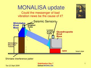
ATF2 Final focus region Final Focus Quadrupole Shintake Monitor Advanced Test Facility (Japan)
Stabilisation monitoring • Between neighbouring accelerator components • Most important is the vertical component • Resolution target nm • Typical range up to 10 m
Straightness monitor concept Monitoring grid • Displacements along 8 interferometer lines Compact Straightness Monitor (CSM)
Distance Meter Interferometers Simulated fringe pattern – as would be seen on a camera • 2 techniques deployed together in same interferometer • Frequency Scanning Interferometry (FSI) – range • Fixed Frequency Interferometry (FFI) - changes
Intensity Interferometer operation Interferometer phase is calculated from fibre intensity: One photodiode per fibre
System data flow overview Control SOFTWARE HARDWARE + SOFTWARE Length Measurement System Grid Recon. SOFTWARE “Alignment” Temperature/Pressure Alignment model
Summer projects 2008 • Data read out for our hardware • FPGA programming • USB control and readout • Understanding the interferometer grid • Multilateration • Piezo and retroreflector calibration • Data display and analysis • Employing LiCAS Analysis Framework
ΔD = (c/2πν) ΔΦ D = (c/ 2π) (ΔΦ/Δnu) D = R (ΔΦ/Δθ) Fixed Frequency Interferometry Frequency Scanning Interferometry Interferometer operation Phase = 2π (Optical Path Distance) / Wavelength Φ = 2π D / λ = 2π D (ν / c) R = (c/ 2π) (Δθ/Δnu)
Solenoid return yoke Final Vertically Focussing Quadrupole Distance Meter Straightness Monitor Geometry Measure movement of QD0s with respect to some points radially outwards through detector field yoke Then must measure the relative motion of these end points Exact geometry to be determined in synch with detector design Detail for single QDzero
Solenoid return yoke Straightness monitor concept Final Vertically Focussing Quadrupole Geometry Measure movement of QD0s with respect to some points radially outwards through detector field yoke Then must measure the relative motion of these end points Exact geometry to be determined in synch with detector design