Download
1 / 26
260 likes | 387 Views
Ion-neutral Coupling in Solar Prominences. Holly Gilbert: NASA GSFC. LASCO C2 on January 4, 2002. Extreme ultraviolet Imaging Telescope (EIT) 304Å on February 2, 2001.

E N D
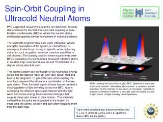
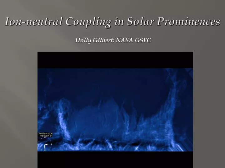
Ion-neutral Coupling in Solar Prominences Holly Gilbert: NASA GSFC
LASCO C2 on January 4, 2002 Extreme ultraviolet Imaging Telescope (EIT) 304Å on February 2, 2001 SDO AIA composite made from three of the AIA wavelength bands, corresponding to temperatures from .7 to 2 million degrees (hotter = red, cooler = blue).
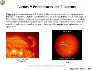
Prominences Filaments • Length ~ 10 - 1000 Mm, Height ~ 1 - 100 Mm, Width ~ 1 - 10 Mm (1 Mm = 1000 km = 108 cm) • Lifetime ~ hours - months • T < 104 K, N ~ 1010 cm-3, M ~ 1015 gm • V ~ 5 - 100 km s-1
Some fundamental questions • How are prominences formed? • Are there fundamental differences between the various types (active region vs. quiescent)? • What drives prominence evolution? • What causes eruption? • Does prominence density, magnetic structure, & pre-eruptive dynamics tell us something fundamental about the magnetic structure and available energy of the CME?
Motivation: • Understanding prominence support • Understanding prominence mass loss • Observations of vertical flows: do ion-neutral interactions play a role? • By understanding the ion-neutral coupling what can we infer about the magnetic structure?
z g y B x Mass loss via. Cross field diffusion(Gilbert et al. 2002; 2007)
Force Balance in a Multi-Constituent Prominence Plasma General Momentum Balance Equation ( jthparticle species) • Other assumptions: • Neglect flows along the magnetic field • Constant density and temperature throughout system • Collision frequencies appropriate for subsonic flow speeds (our calculated flow speeds are less than 0.1 km s-1 ) • Local magnetic field is exactly horizontal to the (locally flat) solar surface
EXAMPLE: Proton Force Balance z-component: y-component: B = Bêx g = -êzGM/r2 Ωj= ZjeB/mj
Perpendicular Flow in a H-He Prominence Plasma z g g B y B x Secondary drifts Tertiary drifts Primary drifts
Parameter Study Considered dependence of particle velocities on variation of several parameters (reference values in parentheses): • Total atom density (1010 cm-3) • Helium abundance by number (0.1) • H and He ionization fractions (0.5 and 0.1) • Temperature (7 x 10³ K) • Magnetic field (10 G)
(a) Total Atom Density 6 6 (b) Helium Abundance 5 5 He He log 10 [ – uz (cm s-1) ] 4 4 H 3 3 H 2 2 1 1 0 0 log 10 [ n (cm-3) ] 8 9 10 11 12 0 .05 .10 .15 .20 .25 .30 .35 .40 Helium Abundance by Number 6 6 (c) Hydrogen Ionization (d) Helium Ionization 5 5 He He 4 4 log 10 [ – uz (cm s-1) ] 3 3 H H 2 2 1 1 0 0 0.1 0.2 0.3 0.4 0.5 0.6 0.7 0.8 0.9 0 .05 .10 .15 .20 .25 .30 .35 .40 Hydrogen Ionization Fraction Helium Ionization Fraction 6 6 (e) Temperature (f) Magnetic Field 5 5 He He 4 4 log 10 [ – uz (cm s-1) ] 3 3 H H 2 2 1 1 0 0 4 5 6 7 8 9 10 2.5 5.0 7.5 10.0 12.5 15.0 17.5 20.0 Temperature (T in units of 103 K) Magnetic Induction (B in units of Gauss)
Time Scales for Neutral Atom Loss Loss Times for Helium and Hydrogen ~1 day Helium: ~ 22 days Hydrogen:
Ha(l=656 nm) January 30, 2000, 20:11:22 UT He I (l=1083 nm) January 30, 2000, 20:10:15 UT Both Images from the HAO Mauna Loa Solar Observatory
Initial Comparison of H and He Observations Ha (l=656 nm) He I (l=1083 nm) Ha (l=656 nm) He I (l=1083 nm) Ha (l=656 nm) He I (l=1083 nm) Ha (l=656 nm) He I (l=1083 nm) He I (l=1083 nm) Ha (l=656 nm)
Quantitative Analysis Gilbert, Kilper, & Alexander, ApJ 671, 2007 • Study temporal and spatial Changes in the relative H and He in filaments via the absorption and He I / Hα absorption ratio • Chose large/stable and small/stable filaments that could be followed across the solar disk • Used co-temporal Hα (6563 Å) and He I (10830 Å) images from the Mauna Loa Solar Observatory in 2004 • Kilper (Master’s thesis) Developed an IDL code that scales and aligns each pair of images, selects the filament, and calculates the absorption ratio at every pixel • Alignment of images is key to a pixel-by-pixel comparison
He/H absorption Darker pixel ↔ Helium deficit Brighter pixel ↔ Helium surplus “Edge effects”
“Large & stable” January 2004
What do we expect?? Geometrical considerations: the simplest picture Cylindrical representation of a filament Filament axis Larger vertical column density View along filament axis Small vertical column density Dark = relative He deficit Top view at disk center
Somewhat more realistic geometry Dark = relative He deficit Top edge with dark band Top edge with dark band Bottom edge with white bands Bottom edge with white bands White = relative He surplus Observed neareast limb west limb center disk
Interpretation of “Edge effects” • Far from disk center, one edge is at the top, and one at the bottom (where the barbs appear) • In a relatively stable filament, He drains out of the top rapidly (relative He deficit) • He draining out of bottom is replaced by He draining down from above (no relative He deficit)
Diffusion timescales In the context of filament threads….. Coronal plasma in between threads Coronal plasma can readily ionize neutral material draining into it Expect very short draining timescales….. However…… For high density filament threads, draining timescale will not be too small– it depends on vertical column density
Ongoing related work • LWS TR&T Focused Science Team on Plasma Neutral Gas Coupling • Chromosphere component; • My team: prominences • Phil Judge: Thermal & magnetic models for ion-neutral chromospheric studies • James Leake: Modeling effects of ion-neutral coupling on reconnection & flux ememergence in chromosphere
LWS TR&T Focused Science Team on Plasma Neutral Gas Coupling • Ionosphere component; • Geoffrey Crowley: Thermosphere-ionosphere • Jiuhou Lei: Ion-neutral processes in the equatorial F-region • Wenbin Wang: Global ionospheric electric field variations
Key questions to be addressed • What physical mechanism(s) set the cross-field scale of prominence threads? • Are ion-neutral interactions responsible for vertical flows and structure in prominences?
Approach Use idealized studies to develop physical insight into core processes: • Cross-field diffusion • Thermal nonequilibrium • Rayleigh-Taylor instability Advance to full multidimensional modeling Utilize observations to guide and test new physical insights