Download
1 / 34
350 likes | 971 Views
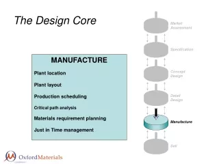
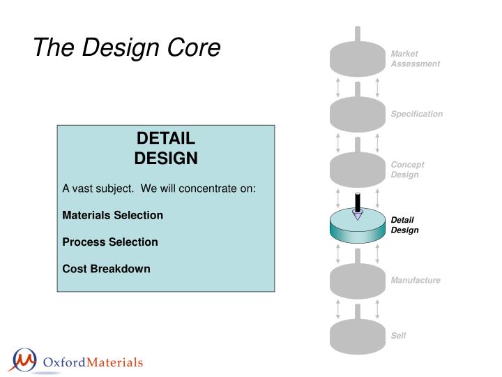
The Design Core. Market Assessment. Specification. DETAIL DESIGN A vast subject. We will concentrate on: Materials Selection Process Selection Cost Breakdown. Concept Design. Detail Design. Manufacture. Sell. FUNCTION. SHAPE. SHAPES FOR TENSION, BENDING, TORSION, BUCKLING

E N D
The Design Core Market Assessment Specification DETAIL DESIGN A vast subject. We will concentrate on: Materials Selection Process Selection Cost Breakdown Concept Design Detail Design Manufacture Sell
FUNCTION SHAPE SHAPES FOR TENSION, BENDING, TORSION, BUCKLING -------------------- SHAPE FACTORS -------------------- PERFORMANCE INDICES WITH SHAPE MATERIAL PROCESS Materials Selection with Shape
I = Second moment of area where y is measured vertically by is the section width at y K = Resistance to twisting of section (≡ Polar moment J of a circular section) where T is the torque L is the length of the shaft θ is the angle of twist G is the shear modulus Moments of Sections: Elastic A = Cross-sectional area
Z = Section modulus where ym is the normal distance from the neutral axis to the outer surface of the beam carrying the highest stress Q = Factor in twisting similar to Z where is the maximum surface shear stress Moments of Sections: Failure
TORSION Torsional stiffness of a beam where L is the length of the shaft, G is the shear Modulus of the material. Define structure factor as the ratio of the stiffness of the shaped beam to that of a solid circular section with the same cross-sectional area thus: Define structure factor as the ratio of the torsional stiffness of the shaped shaft to that of a solid circular section with the same cross-sectional area thus: so, so, Shape Factors: Elastic BENDING Bending stiffness of a beam where C1 is a constant depending on the loading details, L is the length of the beam, and E is the Young’s modulus of the material
TORSION The highest shear stress, for a given torque T, experienced by a shaft is given by: The beam fails when the torque is large enough for to reach the failure shear stress of the material: The beam fails when the bending moment is large enough for σto reach the failure stress of the material: Define structure factor as the ratio of the failure torque of the shaped shaft to that of a solid circular section with the same cross-sectional area thus: Define structure factor as the ratio of the failure moment of the shaped beam to that of a solid circular section with the same cross-sectional area thus: so, so, Shape Factors: Failure/Strength BENDING The highest stress, for a given bending moment M, experienced by a beam is at the surface a distance ym furthest from the neutral axis:
Shape Factors: Failure/Strength Please Note: The shape factors for failure/strength described in this lecture course are those defined in the 2nd Edition of “Materials Selection In Mechanical Design” by M.F. Ashby. These shape factors differ from those defined in the 1st Edition of the book. The new failure/strength shape factor definitions are the square root of the old ones. The shape factors for the elastic case are not altered in the 2nd Edition.
Comparison of Size and Shape Rectangular sections I-sections SIZE →
1 1 1 1 0.88 0.74 0.77 0.62 Shape Factors
ELASTIC BENDING Shape Factor: Rearrange for I and take logs: Plot logI against logA : parallel lines of slope 2 Efficiency of Standard Sections
BENDING STRENGTH Shape Factor: Rearrange for I and take logs: Plot logI against logA : parallel lines of slope 3/2 Efficiency of Standard Sections
TORSIONAL STRENGTH ELASTIC TORSION Efficiency of Standard Sections N.B. Open sections are good in bending, but poor in torsion
ELASTICTORSION Bending stiffness of a beam: Torsional stiffness of a shaft: Shape factor: Shape factor: so, so, f1(F) · f2(G) · f3(M) f1(F) · f2(G) · f3(M) So, to minimize mass m, maximise So, to minimize mass m, maximise Performance Indices with Shape ELASTIC BENDING
FAILURE IN TORSION Failure when moment reaches: Failure when torque reaches: Shape factor: Shape factor: so, so, f1(F) · f2(G) · f3(M) f1(F) · f2(G) · f3(M) So, to minimize mass m, maximise So, to minimize mass m, maximise Performance Indices with Shape FAILURE IN BENDING
EXAMPLE 1, Elastic bending Performance index for elastic bending including shape, can be written as Ceramics Search Region Engineering Alloys Composites Φ=1 Woods Φ=10 Engineering Polymers A material with Young’s modulus, E and density, ρ, with a particular section acts as a material with an effective Young’s modulus and density Polymer Foams Elastomers Shape in Materials Selection Maps
EXAMPLE 1, Failure in bending Performance index for failure in bending including shape, can be written as Ceramics Composites Search Region Φ=1 Engineering Alloys Woods Φ=√10 Engineering Polymers A material with strength, σf and density, ρ, with a particular section acts as a material with an effective strength and density Elastomers Polymer Foams Shape in Materials Selection Maps
Material Micro-Shape Micro-Shaped Material, ψ + = = + Macro-Shape from Micro-Shaped Material, ψφ Macro-Shape, φ Micro-Shaped Material, ψ Micro-Shape Factors Up to now we have only considered the role of macroscopic shape on the performance of fully dense materials. However, materials can have internal shape, “Micro-Shape” which also affects their performance, e.g. cellular solids, foams, honeycombs.
On expanding the beam, its density falls from to , and its radius increases from to Stiffness of the solid beam: Fibres embedded in a foam matrix Prismatic cells The second moment of area increases to If the cells, fibres or rings are parallel to the axis of the beam then The stiffness of the expanded beam is thus Shape Factor: Concentric cylindrical shells with foam between Micro-Shape Factors Consider a solid cylindrical beam expanded, at constant mass, to a circular beam with internal shape (see right).
Function Index Objective Tie Constraint Minimum cost Minimum weight Maximum stored energy Minimum environmental impact Beam Stiffness Strength Fatigue Geometry Shaft Index Column Mats. Selection: Multiple Constraints Mechanical Thermal Electrical…..
Yield before break Leak before break Minimum strength Materials for Safe Pressure Vessels
M1 = 0.6 m1/2 M3 = 100 MPa Materials for Safe Pressure Vessels Search Region
Multiple Constraints: Formalised • Express the objective as an equation. • Eliminate the free variables using each constraint in turn, giving a set of performance equations (objective functions) of the form: • where f, g and h are expressions containing • the functional requirements F, geometry M • and materials indices M. • If the first constraint is the most restrictive (known as the active constraint) then the performance is given by P1, and this is maximized by seeking materials with the best values of M1. If the second constraint is the active one then the performance is given by P2 and this is maximized by seeking materials with the best values of M2; and so on. • N.B. For a given Function the Active Constraint will be material dependent.
The object function is Constraint 1: Stiffness where so, If the beam is to meet both constraints then, for a given material, its weight is determined by the larger of m1 or m2 Constraint 2: Strength where so, Choose a material that minimizes or more generally, for i constraints Multiple Constraints: A Simple Analysis A LIGHT, STIFF, STRONG BEAM
M1 Limited Domain The selection map can be divided into two domains in each of which one constraint is active. The “Coupling Line” separates the domains and is calculated by coupling the Objective Functions: where CC is the “Coupling Constant”. log Index M2 A A B B Materials with M2/M1>CC , e.g. , are limited by M1 and constraint 1 is active. Materials with M2/M1<CC , e.g. , are limited by M2 and constraint 2 is active. M2 Limited Domain Coupling Line M2 = CC·M1 log Index M1 Multiple Constraints: Graphical Construct a materials selection map based on Performance Indices instead of materials properties.
A box shaped Search Region is identified with its corner on the Coupling Line. Within this Search Region the performance is maximized whilst simultaneously satisfying both constraints. are good materials. Changing the functional requirements F or geometry G changes CC, which shifts the Coupling Line, alters the Search Area, and alters the scope of materials selection. Now and are selectable. M1 Limited Domain M1 Limited Domain Search Area Search Area log Index M2 log Index M2 Coupling Line M2 = CC·M1 A A A B B C C C C C M2 Limited Domain M2 Limited Domain Coupling Line M2 = CC·M1 log Index M1 log Index M1 Multiple Constraints: Graphical
B N Turns Current i L d 2r d Windings for High Field Magnets Upper limits on field and pulse duration are set by the coil material. Field too high the coil fails mechanically Pulse too long the coil overheats
The field (weber/m2) is where μo = the permeability of air, N = number of turns, i = current, λf = filling factor, f(α,β) = geometric constant, α = 1+(d/r), β = L/2r Radial pressure created by the field generates a stress in the coil σmust be less than the yield stress of the coil material σy and hence So, Bfailure is maximized by maximizing Windings for High Field Magnets CONSTRAINT 1: Mechanical Failure
The energy of the pulse is (Re = average of the resistance over the heating cycle, tpulse = length of the pulse) causes the temperature of the coil to rise by where Ωe = electrical resistivity of the coil material Cp = specific heat capacity of the coil material If the upper limit for the change in temperature is ΔTmax and the geometric constant of the coil is included then the second limit on the field is So, Bheat is maximized by maximizing Windings for High Field Magnets CONSTRAINT 1: Overheating
In this case the field is limited by the lowest of Bfailure and Bheat: e.g. Thus defining the Coupling Line Windings for High Field Magnets Pulse length = 10 ms
Search Region: Ultra-short pulse Search Region: short pulse HSLA steels Cu-Be-Co-Ni Cu-Al2O3 Cu-Nb Search Region: long pulse Be-Coppers Cu-Zr GP coppers Cu-4Sn HC Coppers Cu Al-S150.1 Windings for High Field Magnets