Download
1 / 32
320 likes | 426 Views
Development of an Adaptable Monitoring Package for Marine Renewable Energy. James Joslin , Edward Celkis , Chris Roper, Andrew Stewart, Brian Polagye Northwest National Marine Renewable Energy Center University of Washington. MTS/IEEE Oceans 2013 Practice September 18, 2013.

E N D
Development of an Adaptable Monitoring Package for Marine Renewable Energy James Joslin, Edward Celkis, Chris Roper, Andrew Stewart, Brian Polagye Northwest National Marine Renewable Energy Center University of Washington MTS/IEEE Oceans 2013 Practice September 18, 2013
Presentation Overview • Project motivation and background • System description • Design analysis through CFD • Design optimizations • Next Steps and Summary Admiralty Inlet, Puget Sound, WA
Project Motivation • Characterize the environment around marine energy converters through cabled monitoring • Monitor converter performance in real time
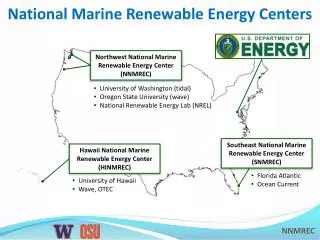
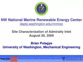
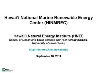
Marine Energy Sites Ocean Currents Admiralty Inlet, Puget Sound, WA Pacific Northwest Newport, Oregon North Energy Test Site Tidal Currents
Sea Spider Instrumentation Package Sea Spider after recovery in August 2011
Design Constraints Constraint Solution Instrument Power and Bandwidth Sensor Maintenance and Adaptability Low Cost Site Conditions Cabled Recoverable Independent of Turbine Shrouded for Low Drag and Maneuverability
System Description • Saab SeaEye Falcon ROV • Lightweight inspection class ROV • Dimensions: 1.0 mx 0.5 mx 0.6 m • Weight: 60 kg in air • Thrust: 50 kgf forward and 13 kgf vertical Current AMP and Millennium Falcon Design Geometry
System Description • Saab SeaEye Falcon ROV • “Millennium” Tool Skid • Augmented thrust capacity • Custom manipulators for deployment and docking operations Current AMP and Millennium Falcon Design Geometry
System Description • Saab SeaEye Falcon ROV • “Millennium” Tool Skid • Adaptable Monitoring Package • Monitoring instrumentation • Wet-mate power and fiber connector • Body shroud for reduced drag Current AMP and Millennium Falcon Design Geometry
AMP Instrumentation • Cameras • Stereo-optical 2mpx cameras • BlueView P900/2500 acoustical camera Current AMP Instrumentation Layout
AMP Instrumentation • Cameras • Strobes Current AMP Instrumentation Layout
AMP Instrumentation • Cameras • Strobes • Hydrophones Current AMP Instrumentation Layout
AMP Instrumentation • Cameras • Strobes • Hydrophones • ADCP Current AMP Instrumentation Layout
AMP Instrumentation • Cameras • Strobes • Hydrophones • ADCP • ADV Current AMP Instrumentation Layout
AMP Instrumentation • Cameras • Strobes • Hydrophones • ADCP • ADV • CTDO Current AMP Instrumentation Layout
AMP Instrumentation • Cameras • Strobes • Hydrophones • ADCP • ADV • CTDO • Vemco Fish Tag Receivers Current AMP Instrumentation Layout
AMP Instrumentation • Cameras • Strobes • Hydrophones • ADCP • ADV • CTDO • Vemco Fish Tag Receivers • C-PODs Current AMP Instrumentation Layout
AMP Deployment Operations RV Jack Robertson Current AMP with Millennium Falcon on “garage” style launch platform during deployment operations
AMP Deployment Operations RV Jack Robertson Current AMP with Millennium Falcon flying from launch platform to docking station
AMP Deployment Operations Current AMP with Millennium Falcon docking station mounted to a turbine
AMP Deployment Operations AMP oriented for viewing turbine wake AMP oriented for viewing support structure AMP oriented for viewing turbine rotor
AMP Design Analysis • Two design cases considered: • During deployments with the “Millennium” Falcon: mean currents < 1 m/s from ahead • During long term docked operations: mean currents < 5 m/s from the side • Modeled in ANSYS Workbench and Fluent for 3D CFD simulations CFD model for docked operations CFD model for deployments
AMP Design Analysis - Methods • CFD results analysis: • Cross-sectional area normal to flow, A [m2] • Lift and drag coefficients of full system and subcomponents: • Center of pressure, (x, y, z) coordinates • CFD sensitivity studies: • Meshing refinements: Coarse, Medium, and Fine • Input velocity: 0.5 m/s, 1.0 m/s, and 1.5 m/s • Experimental and field validation Model free body diagram ANSYS fluid domain meshing
AMP Design Analysis - CFD Results • Sensitivity study variability in drag force: • Grid dependence: < 3.50% • Velocity dependence: < 1.1% Normalized velocity with streamlines over the body surfaces Total pressure [Pa] on the body surfaces
AMP Design Optimizations Drag forces on AMP and “Millennium” Falcon in a head-on current of 1 m/s. Cd ≅ 0.67 AMP components Drag forces and coefficients of the AMP by component
AMP Design Optimizations Maximum current with combined thrust of 100 kgf = 1.8 m/s Drag force vs. current with maximum available thrust (red line)
AMP Design Optimizations Case study of design improvement analysis through CFD: Drag forces in 5 m/s side-on currents: up to 3150lbf! AMP with rotating strut fairings Drag forces and coefficients on AMP Components
AMP Design Optimizations Case study of design improvement analysis through CFD: Rotating struts reduces drag forces by 54% (1400 lbf) AMP with rotating strut fairings Drag forces and coefficients on AMP Components
Next Steps • AMP and “Millennium” structural design • Stability analysis • Subscale modeling for flume and wind tunnel experiments • Full scale open water testing 1/8 th Subscale Model in Flume
Summary • AMP design for monitoring marine renewable energy projects • “Millennium” Falcon deployment ROV for operations in moderate (<1 m/s) currents • CFD design analysis and optimization: • Current design should be able to overcome currents up to 1.8 m/s • Drag reduction for side-on currents of up to 54% by allowing strut fairings to rotate. AMP deployment sequence
Questions? • Funding for this project is provided by the US Department of Energy and Public Utility District No. 1 of Snohomish County. • We would also like to thank: • From APL: Russ Light, Vern Miller, Eric Boget, Trina Litchendorf, Ben Rush, Dave Dyer • Danny Miles and Eric Schneider (SnoPUD), Geoff Cook (SeaView), Jack Roberts (SymphoticTii)
Evaluating CFD Results • Wall Y+ Values • Non-dimensional distance from a wall bounded flow. • Comparison to Literature • Run simulations with the same configuration as similar studies that have been validated. • Experimental Evaluation • Subscale testing in the flume. • Full scale testing in open water. Wall Y+ Values on AMP Body