Download
1 / 68
980 likes | 1.53k Views
ENG3640 Microcomputer Interfacing. Week #1 Introduction to Interfacing and Microcontrollers (M68HC12). Resources. Huang, Chapter 1 Sections 1.2 Number System Issue 1.3 Computer Hardware Organization 1.4 Memory 1.6 Program Execution

E N D
ENG3640 Microcomputer Interfacing Week #1 Introduction to Interfacing and Microcontrollers (M68HC12)
Resources • Huang, Chapter 1 Sections • 1.2 Number System Issue • 1.3 Computer Hardware Organization • 1.4 Memory • 1.6 Program Execution • 1.7 Overview of the HCS12 Microcontroller • 1.8 The HCS12 CPU Registers • 1.9 HCS12 Address Modes • 1.11 A Sample of HCS12 Instructions ENG3640 Fall 2012
Topics • Interfacing: Definition • Microcontrollers • M68HC12 Architecture ENG3640 Fall 2012
Definitions of “interface” from Webster’s Dictionary: noun: the place at which independent systems meet and act or communicate with each other. e.g. (1) human - machine interface (2) Digital - analogue interface (3) Digital - digital interface TTL - CMOS interface Parallel - Serial interface Interfaces and Interfacing ENG3640 Fall 2012
Digital- Human- Machine Analogue Interface Interface System-Level Interfaces Human Users Analogue Environment Digital-Digital Interface Other Digital Systems Human-machine interface: Input devices: keyboard, mouse, microphone, camera Output devices: CRT, printer, light panel, audio amp. Digital - Analogue Interface: Input devices: A/D converters, modems, sensors Output devices: D/A converters, modems, transducers, actuators, stepper motors Control devices: switches, multiplexers, amplifiers, attenuators Digital - Digital Interface: Connectors: wires, ribbon cable, coax, twisted pair, PCB I/O devices: buffers, level-shifters, synchronizers ENG3640 Fall 2012
Interfaces and Interfacing Informal Definition The physical, electrical and logical means of exchanging Information with a functional module. The process of enabling a computer to communicate with the external world through Software, Hardware and Protocols. ENG3640 Fall 2012
Why is computer interfacing important ? • The human-machine interface determines the ultimate success or failure of many computer based systems (Apple iPhone) • Digital systems exist within and must successfully interact with an analogue natural environment. • Digital-Analogue interfaces are unavoidable • Rather than designing digital systems from elementary components, computer engineers more typically assemble new systems from existing sub-systems. ENG3640 Fall 2012
Typical Interfacing Activities • Selecting software/hardware subsystems that can (at least potentially) interact well with each other. • Appropriate D/A and A/D converters (speed, accuracy, …) • Serial vs. parallel communication. • Determining appropriate hardware connections: • Cabling, connectors, drivers, receivers, correct termination, etc. • Resolving any hardware incompatibilities. • CMOS with TTL • Configuring hardware interfaces correctly using low-level software drivers. • LCD, Keypads in embedded systems. • Interfacing software components correctly; • Selecting compatible software versions; • Calling the correct procedures in the correct sequence with the correct parameters. ENG3640 Fall 2012
Hardware Interfaces within a Personal Computer (PC) (greatly simplified) Serial Port Controller Lab Board Keyboard CPU Cache Mouse Memory Controller Main Memory Parallel Port Controller Printer Hard Drive Disc Controller Diskette Drive Diskette Controller Video Controller CRT System Bus ENG3640 Fall 2012
What is a Microcontroller? • The Central Processing Unit (CPU)? • The Microprocessor Unit? • The Microcomputer System? • The Microcontroller Unit (MCU)? ENG3640 Fall 2012
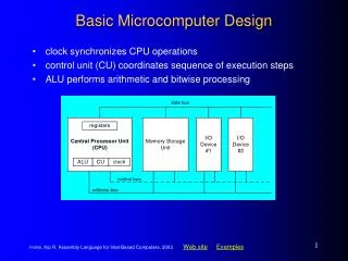
Micro Computer System: 5 Basic Units • The Arithmetic Logic Unit (ALU) • Control Unit: directs the operation of all other parts. • Memory: Store program & data • Input: Allows data & info to be entered into memory • Output: Transfers data from memory to outside world ENG3640 Fall 2012
The Central Processing Unit (CPU) • CPU executes program instructions • Program counter (PC) is a special register that points to the instructions • Instruction decoder tells the ALU what to do with the data • Control sequencer manages the transfer of instruction and data bytes along the internal data bus ENG3640 Fall 2012
CPU vs. Microprocessor? • A Central Processing Unit (CPU) refers to the integration of an ALU and Control. • A Microprocessor refers to the implementation of the CPU functions in a single large scale integrated circuit (IC). ENG3640 Fall 2012
The MicroComputer System • MicroComputer has 3 basic parts connected by an internal bus • CPU • Memory • Registers • I/O registers • data, control, status • I/O port is a collection of I/O pins on the chip that represents a unit of data Block diagram of a typical microcontroller shown in single-chip mode ENG3640 Fall 2012
Micro Computer vs. Micro Controller? • A Micro Controller is a Micro Computer with its memory and I/O integrated into a single chip! ENG3640 Fall 2012
Input Port Data Transfer CPU OR Sensor MEMORY Port’s Register The Microcontroller Unit (MCU)Example of an Input Operation ENG3640 Fall 2012
Output Port Data Transfer CPU Instrument Panel Port’s Register The Microcontroller Unit (MCU)Example of an Output Operation ENG3640 Fall 2012
Set Counter to count on ↑ edges Speed Signal CPU reads counter at every time interval CPU Counter Speed Sensor Timer Program timer’s interrupt interval The MCU: Applications ENG3640 Fall 2012
Principle In 1945, the mathematician Von Neumann (VN) demonstrated in study of computation that a computer could have a simple structure, capable of executing any kind of program, given a properly programmed control unit, without the need of hardware modification The Von Neumann Computer ENIAC - The first electronic computer (1946) ENG3640 Fall 2012
Structure A memory for storing program and data. The memory consists of the word with the same length A control unit (control path) featuring a program counter for controlling program execution An arithmeticand logic unit (ALU) also called data path for program execution The Von Neumann Computer Processor or Central processing unit Memory Datapath Data and Instructions Data Registers Controllpath Address register Instruction register PC Address ENG3640 Fall 2012
The Von Neumann Computer Coding A program is coded as a set of instructions to be sequentially executed Program execution Instruction Fetch (IF): The next instruction to be executed is fetched from the memory Decode (D): Instruction is decoded (operation?) Read operand (R): Operands read from the memory Execute (EX): Operation is executed on the ALU Write result (W): Results written back to the memory Instruction execution in Cycle (IF, D, R, EX, W) ENG3640 Fall 2012
Embedded Systems • Any device or collection of devices that contain one of more dedicated computers, microprocessors, or micro-controllers • Combination of computer hardware and software designed to perform a specific function • Broad definition: • Any computing system that is not a desktop computer ENG3640 Fall 2012
Embedded Systems: Examples ENG3640 Fall 2012
Typical Microcontroller Embedded Application • The amount of air and fuel and timing of the ignition system determine the fuel efficiencyand amount of exhaust emission. • Input sensors are used as feedback to correct any error. • Microcontroller uses the sensor inputs to control the ignition system to MAX fuel efficiency and MIN exhaust emissions. Microcontroller used to control air/fuel mixture in an automotive engine ENG3640 Fall 2012
History of Micro Controllers • 1974 Intel produced first microprocessor 4004 • 1977 Intel introduced several microcontrollers 8051, 8032 • 1978 Motorola introduced 6801, RAM , ROM, EPROM 6805 • 1985 Motorola introduced the 6811 micro controller (8-bit CPU, 8K ROM, 256Byte RAM, 512Byte EEPROM) • 1997 Motorola introduced the 68HC12 which is upward compatible with the 6811 ENG3640 Fall 2012
1-KB SRAM 4-KB EEPROM 68HC812A4 Block Diagram CPU12 ENG3640 Fall 2012
Features of the 68HC12 Microcontroller • 16-bit CPU • 64 kB memory space • 768 bytes to 4 kB of EEPROM • 1 kB to 12 kB of on-chip SRAM • 32 kB to 128 kB flash memory • Sophisticated timer functions that include: • input capture, output compare, • pulse accumulators, real-time interrupt, and COP timer • Serial communication interfaces: SCI, SPI, CAN, BDLC • Background debug mode (BDM) • 8-bit or 10-bit A/D converter • Instructions for supporting fuzzy logic function ENG3640 Fall 2012
On-Chip Memory • 1Kbyte of static RAM • Re-mappable and removable • 4 Kbytes of EEPROM • individually byte writable (~10ms) • bulk erase possible ENG3640 Fall 2012
Registers in the CPU Model ENG3640 Fall 2012
Accumulators • AccumulatorsA and B are general-purpose 8-bit accumulators that contain operands and results of arithmetic calculations or data manipulations. • Accumulator Dis the concatenation of accumulators A and B. • Some instructions treat the combination of these two 8-bit accumulators as a 16-bit double accumulator. ENG3640 Fall 2012
Index Registers • Index registers X and Y are used for indexed addressing. • Indexed addressing adds the value in an index register to a constant or to the value in an accumulator to form the effective address of the operand. • Index registers X and Y can also serve as temporary data storage locations with some combinational capability. ENG3640 Fall 2012
Program Counter • The program counter (PC) contains the address of the next instruction to be executed. • The program counter can also serve as an index register in all indexed addressing modes except auto increment and auto decrement. ENG3640 Fall 2012
Stack Pointer • The stack pointer (SP) contains the last stack address used. • The CPU12 supports an automatic program stack that is used to save system context during subroutine calls and interrupts. • The stack pointer can also serve as a temporary data storage location or as an index register for indexed addressing. ENG3640 Fall 2012
Z — Zero Flag • The Z flag is set when the result of an operation is all 0s. • V — Two’s Complement Overflow Flag • The V flag is set when a two’s complement overflow occurs. • C — Carry/Borrow Flag • The C flag is set when an addition or subtraction operation produces a carry or borrow. Condition Code Register ENG3640 Fall 2012
H — Half-Carry Flag • The H flag is used only for BCD arithmetic operations. It is set when an ABA, ADD, or ADC instruction produces a carry from bit 3 of accumulator A. The DAA instruction uses the H flag and the C flag to adjust the result to correct BCD format. • I — Interrupt Mask Bit • Setting the I bit disables maskable interrupt sources. • N — Negative Flag • The N flag is set when the result of an operation is less than 0. ENG3640 Fall 2012
S — Stop Disable Bit • Setting the S bit disables the STOP instruction. • X — XIRQ Interrupt Mask Bit • Setting the X bit masks interrupt requests from the XIRQ pin. ENG3640 Fall 2012
Memory Map ENG3640 Fall 2012
Register Block • memory block reserved for internal registers • from $00 to $F4 used; $F5 reserved up to $1FF (512 memory locations) • can be moved to any 2K boundary from initial location of $0000 using INITRG ($11) • used for controlling all CPU and peripheral functions including status, input and output ENG3640 Fall 2012
Memory Map on EVB ENG3640 Fall 2012
Steps to Execute a Program Fetch op-code (instruction) Decode op-code Fetch operand address Execute instruction Examples LDDA #$10 STAA $4000 LDAB $10 STAA $4000 ENG3640 Fall 2012
Prefixes for Number Bases • A number (operand) can be represented in binary, octal, decimal, or hexadecimal format. • An appropriate prefix is added in front of the number to indicate its base. ENG3640 Fall 2012
Addressing Modes • A 68HC12 instruction consists of one or two bytes of opcode and zero to five bytes of operand addressing information. • Addressing Modes: determines HOW the CPU access memory locations to be acted upon. • Examples: • Inherent Mode • Immediate Mode • Direct Mode • Extended Mode • Relative Mode • Indexed Mode ENG3640 Fall 2012
Inherent Mode • Instructions that use this addressing mode either have no operands or all operands are in internal CPU registers • In either case the CPU does not need to access any memory location to complete the instruction. • Examples: • NOP No Operation • DECA Decrement Accumulator A ( A = A – 1) • INX Increment Index Register ( X = X + 1) ENG3640 Fall 2012
Immediate Mode • Operands for immediate mode instructions are included in the instruction stream. • The CPU does not access memory when this type of instruction is executed. • An immediate value is preceded by a # character in the assembly instruction. • Examples: • LDAA #$55 ; A $55 ; place the value $55 in ACC A • LDX #$2000 ; X $2000 ; place the value $2000 in Index Reg X ENG3640 Fall 2012
Direct Mode • This addressing mode is used to access operands in the address space range of $0000 - $00FF. • Since these addresses begin with $00, only the eight low-order bits of the address need to be included in the instruction which saves program space and execution time. • Examples: • LDAA $55 ; A m[$55] ; fetches the contents of the memory location ; at $0055 and puts it in ACC A ENG3640 Fall 2012
Instruction Set • The instruction set of the 68HC12 contains different types of instructions: • Load & Store Instructions • Transfer & Exchange Instructions • Move Instructions • Add & Subtract Instructions • Multiply & Divide Instructions ENG3640 Fall 2012
Load & Store Instructions ENG3640 Fall 2012
Transfer & Exchange Instructions • Transfer instructions copy the contents of a register or accumulator into another register or accumulator. • Examples: • TAB ; Transfer A to B (A) B • TBA ; Transfer B to A (B) A • NOTE: Source contents not changed by the operation. • Exchange instructions exchange the contents of pairs of registers or accumulators • Example: • EXG A,B ; Exchanges contents of A and B ENG3640 Fall 2012
Add & Subtract Instructions ENG3640 Fall 2012
Move Instructions • These instructions move data bytes or words from a source (M1) to a destination (M2) in memory. • Example: • MOVB $1000, $2000 ; copies the contents of the ; memory loc $1000 to loc $2000 ENG3640 Fall 2012