Download
1 / 10
100 likes | 187 Views
Polarised foreground removal using Faraday tomography - recovering the EoR signature. Testori et al. (2004) Wolleben et al. (2005). Testori et al. (2004), Wolleben et al. (2005). Paul M Geil (U. Melb.) Bryan M Gaensler (U. Syd.). Outline. Problem Strategy Preliminary results

E N D
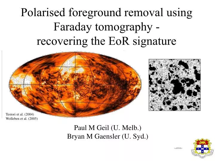
Polarised foreground removal using Faraday tomography - recovering the EoR signature Testori et al. (2004) Wolleben et al. (2005) Testori et al. (2004), Wolleben et al. (2005) Paul M Geil (U. Melb.) Bryan M Gaensler (U. Syd.)
Outline • Problem • Strategy • Preliminary results • Further considerations MWA project meeting - Mt Stromlo
EoR signal in Stokes I buried under non-polarised foreground emission • Gain errors & non-ideal feeds conspire to contaminate I further (instrumental polarisation or leakage) I´ = IEoR + INPFG + L · P P = Q + iU (complex linear polarisation) So… • How can we distinguish between leakage and EoR signal? • How can we remove contamination in I by polarised foregrounds? Problem MWA project meeting - Mt Stromlo
RM synthesis or spectro-polarimetry(Burn 1966; Killeen et al. 2002; Brentjens & de Bruyn 2005) Exploits the Fourier relationship: P(2) F() Fourier pair: (2, ) Faraday depth very long ‘baselines’ in 2 space high ‘resolution’ in space Strategy (RM synthesis) MWA project meeting - Mt Stromlo
Single baseline e.g. Stokes I (non-polarised + EoR signal) • Full array (N antennae) + conjugate ∑ baselines required due to S/N requirements Strategy (Mueller transformation) Coherency Stokes representation : Mueller operator (Hamaker-Sault notation) MWA project meeting - Mt Stromlo
Cleaning algorithm: cf. Hogbom (1974) identify largest peak in |FI|() fit for max, FI (max) & (02) subtract corresponding RM spread function R() (with loopgain) Continue until |FI|() peaks meet threshold criteria (‘S/N’ in |FI|) e.g. signal fit Strategy (removal) MWA project meeting - Mt Stromlo
Jelic et al. (2008) Simulation & modelling (sources) See, for example: Geil et al. (MNRAS 390, 1496, 2008) Jelic et al. (astro-ph:0804.1130v3, 2008) McQuinn et al. (ApJ 653, 815, 2006) MWA project meeting - Mt Stromlo
Simulation & modelling (instrumental) • Channel depolarisation • Beam depolarisation • Frequency dependent leakage • Altitude/sky position dependence • 3d power spectra The integrated complex polarisation over each frequency channel will suffer from depolarisation due to the deconstructive summation of linear polarisation vectors within the small but finite range of frequencies in each channel. Unresolved polarised sources within the beam will superimpose detructively. This effect should be included in the simulations due to finite size the synthesised beam. MWA project meeting - Mt Stromlo
Model EoR signal ionisation field (slice @ 154 MHz) Tb profile (central los) Preliminary results Smooth non-polarised FG already removed using log-polynomial fit Example: B = 8 MHz centred on 154 MHz MWA project meeting - Mt Stromlo
Thank you Comments, questions & suggestions are very welcome (pmgeil@unimelb.edu.au) MWA project meeting - Mt Stromlo