Download

1 / 71
710 likes | 792 Views
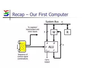
Our First Real System. Review. On our way to building a computer…. Represent Info with 0’s & 1’s (aka bits). Logic Circuits: Universal Method. 0’s & 1’s. Memory Circuits. Computers. We are here. The System Clock. “500 Mhz Pentium III computer…” What does “500 Mhz” mean?

E N D
Review On our way to building a computer… Represent Info with 0’s & 1’s (aka bits) Logic Circuits: Universal Method 0’s & 1’s Memory Circuits Computers We are here
The System Clock • “500 Mhz Pentium III computer…” • What does “500 Mhz” mean? • It refers to the speed of theSystem Clock.(actually this is only one of the clocks…) • All digital systems have such “Clocks,” even traffic lights and elevator control systems.
Clocks: Some Terminology • Think of System Clock as a heart. • How fast it beats is measured in Hertz (Hz) which means “cycles per second” • Prefixes: • Kilo = 1,000 • Mega = 1,000,000 • Giga = 1,000,000,000
The System Clock (cont.) • Rough idea: System takes a “step” every time the System Clock beats. • We’ll see how this works in an example. • In real life, Clock is a Quartz crystal,which sends out 0’s and 1’s on a wire. • In every cycle, it changes from 0 to 1 and back to 0 0
The System Clock (cont.) • Rough idea: System takes a “step” every time the System Clock beats. • We’ll see how this works in an example. • In real life, Clock is a Quartz crystal,which sends out 0’s and 1’s on a wire. • In every cycle, it changes from 0 to 1 and back to 0 1
The System Clock (cont.) • Rough idea: System takes a “step” every time the System Clock beats. • We’ll see how this works in an example. • In real life, Clock is a Quartz crystal,which sends out 0’s and 1’s on a wire. • In every cycle, it changes from 0 to 1 and back to 0 0
Our System: A Traffic Light
A Traffic Light • Intersection of two one-way roads
A Traffic Light • Intersection of two one-way roads A B Car Sensors
Traffic Light System Clock • Traffic Lights don’t have to act very fast. • Let’s say the System Clock only beatsonce every 4 seconds. • This is 0.25 Hz.(a few Billion times slower than your PC)
Traffic Light Design • How do we go about designing the Traffic Light? • First, let’s think about all the possible States of the traffic light.
Traffic Light • Intersection of two one-way roads A B Car Sensors
Light A Light B
Possible States Light A Light B
Possible States Light A Light B
Possible States Light A Light B
Possible States Light A Light B
Actually Only 4 Possibilities Light A Light B
Traffic Light Design • We figured out some possible States of the Traffic Light. • Next, we should think logically about how the Traffic Light should behave. • For now, we will try to keep it simple. • (Suppose these are infrequently used country roads.)
How should the Light behave? A Light A B Car Sensors Light B
Traffic Light Behavior IF A=1 AND B=0 Light A Light B
Traffic Light Behavior Otherwise IF A=1 AND B=0 Light A Light B
Traffic Light Behavior Otherwise IF A=1 AND B=0 Light A Always Light B
Traffic Light Behavior Otherwise IF A=1 AND B=0 Light A Always IF A=0 AND B=1 Otherwise Light B
Traffic Light Behavior Otherwise IF A=1 AND B=0 Light A Always Always IF A=0 AND B=1 Otherwise Light B
Traffic Light Behavior Otherwise Note:Clock beats every 4 sec.So Light is Yellow for 4 sec. IF A=1 AND B=0 Light A Always Always IF A=0 AND B=1 Otherwise Light B
Traffic Light State Machine Otherwise Note:Clock beats every 4 sec.So Light is Yellow for 4 sec. IF A=1 AND B=0 Light A Always Always IF A=0 AND B=1 Otherwise Light B
Traffic Light Design • We’ve figured out the logical behavior of the Traffic Light in terms of a State Machine: • We know what the states are. • For each state, given any input,we know which state to go to next. • How do we build it?
Traffic Light Design • Thinking this through: • Our machine needs to:
Traffic Light Design • Thinking this through: • Our machine needs to: • Remember which state it is in (Memory)
Traffic Light Design • Thinking this through: • Our machine needs to: • Remember which state it is in (Memory) • Given the state it is in and input values, it must determine which state to go tonext (Logic)
Traffic Light Design • Thinking this through: • Our machine needs to: • Remember which state it is in (Memory) • Given the state it is in and input values, it must determine which state to go tonext (Logic) • And that’s all !
Traffic Light Design • Problem 1: • Remember which state it is in (Memory) • How do represent the states? • We could keep one bit of memory for whether Light A is Green or not, whether it is Yellow or not, … • This would take 6 bits of memory. • There is a much simpler way!
Traffic Light Design • Problem 1: • Remember which state it is in (Memory) • How do represent the states? • Answer: • Just number them (using binary numbers). • We have 4 states. • Call them 00, 01, 10, 11. • We (human designers) will keep track of what these names mean.
Traffic Light States Otherwise IF A=1 AND B=0 Light A Always Always IF A=0 AND B=1 Otherwise Light B
Traffic Light States Otherwise IF A=1 AND B=0 01 00 Light A Always Always IF A=0 AND B=1 11 10 Otherwise Light B
Traffic Light Design • Problem 2: • Given the state it is in and input values, it must determine which state to go tonext (Logic) • Answer:
Traffic Light Design • Problem 2: • Given the state it is in and input values, it must determine which state to go tonext (Logic) • Answer: • Build a Truth Table • Use Universal Method!
M1 M2 ABD1 D2Light A Red Light B Red … Traffic Light Behavior Build A Truth Table for next state / Output
Traffic Light Behavior Otherwise IF A=1 AND B=0 01 00 Light A Always Always IF A=0 AND B=1 11 10 Otherwise Light B
M1 M2 ABD1 D2Light A Red Light B Red … 0 0 1 0 0 1 1 0 Traffic Light Behavior Build A Truth Table for next state / Output
Traffic Light Behavior Otherwise IF A=1 AND B=0 01 00 Light A Always Always IF A=0 AND B=1 11 10 Otherwise Light B
M1 M2 ABD1 D2Light A Red Light B Red … 0 0 1 0 0 1 1 0 0 1 * * 1 0 1 0 Traffic Light Behavior Build A Truth Table for next state / Output