Download
1 / 8
90 likes | 262 Views
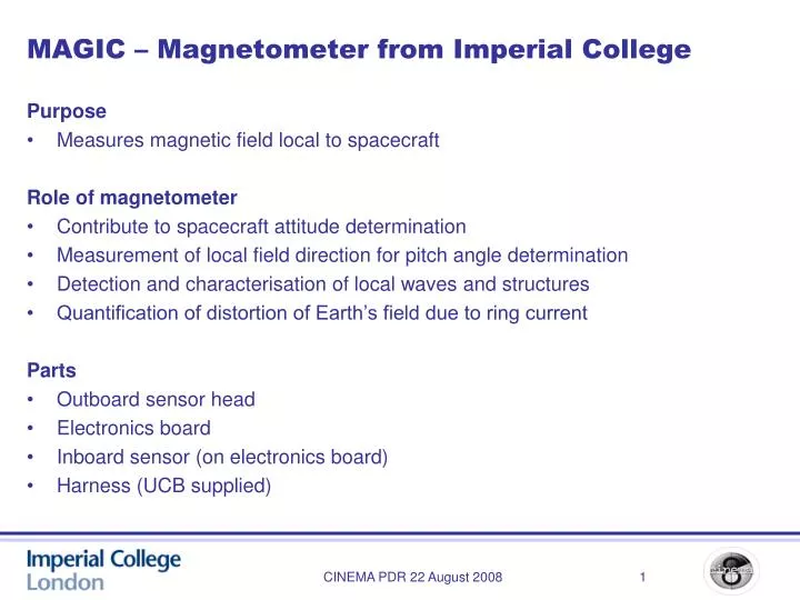
MAGIC – Magnetometer from Imperial College. Purpose Measures magnetic field local to spacecraft Role of magnetometer Contribute to spacecraft attitude determination Measurement of local field direction for pitch angle determination Detection and characterisation of local waves and structures

E N D
MAGIC – Magnetometer from Imperial College Purpose • Measures magnetic field local to spacecraft Role of magnetometer • Contribute to spacecraft attitude determination • Measurement of local field direction for pitch angle determination • Detection and characterisation of local waves and structures • Quantification of distortion of Earth’s field due to ring current Parts • Outboard sensor head • Electronics board • Inboard sensor (on electronics board) • Harness (UCB supplied) CINEMA PDR 22 August 2008
0V 16V 3.3 or 5V PSU Vout Vin IO DRIVE CLK MR DRV H/W Command Serial Data IN FB Feedback Serial Data Out MAG OUT MR OUT Acquisition MAG ANL CONTROL LOOP ADC CLK MAGNETOMETER ADC SENSOR HEAD MAGIC PCB KEY SIGNAL PRI PWR SEC PWR H/W CMD LINES MAGIC – schematic • Note: only one sensor shown here • Some labelling alignment lost in cut and paste (sorry) CINEMA PDR 22 August 2008
Mechanical Sensor head • Sensor head includes drive circuitry to minimise losses in harness • Sensor head mass: 6-16g • Internal arrangement may change; external dimensions fixed • Measures magnetic field local to spacecraft PCB • 9x9cm , populated both sides, at least 1cm clearance on each side • May include through-axis PCB to accommodate spin axis MR • PCB mass <150g CINEMA PDR 22 August 2008
Harness 18 wires • 3 x 2 Differential Sensor out (Bx, By, Bz) • 3 x 2 Feedback (Bx, By, Bz) • 1 x Thermistor (RTN reference to GND) • 1 x Bridge Voltage (RTN reference to GND) • 1 x Drive Clock (RTN reference to GND) • 1 x Drive Voltage (RTN reference to GND) • 1 x GND • 1 x Vref • Slightly magnetic – last 6cm should be replaced by non-magnetic condutor • Braid connect to chassis ground at each end • MDM connector from harness to MAGIC PCB • No connector at sensor head – direct fit to sensor PCB CINEMA PDR 22 August 2008
Electrical and thermal Voltages • 16V drive • 0V ground • 5V (or 3.3V – TBD) logic and analogue Thermal • Initial modelling suggests -50degC -> +50degC at sensor head (!) • Imperial will undertake early testing of potted sensor over this range • Will also investigate possible use of exterior coatings • May be necessary to provide a flexibility requirement on the harness to counteract the effect of thermal expansion – we will investigate this further CINEMA PDR 22 August 2008
Data and command interface Data • Communication via ADS1216 serial • 3 lines: SLCK, SERIAL DATA IN, SERIAL DATA OUT • Time stamping from s/c • 7 channels: OB (x,y,z), IB (x,y,z), Temperature • 19 bits (-> 0.25nT resolution at +-65536nT) • All instrument control from s/c FPGA or CPU • Sampling rate: 200 samples/s MR, 1 sample/s temperature • Boxcar (or other) averaging and decimation to 10 Hz performed by s/c • All commanding via serial interface Required commanding • Mode switch between Attitude, Science and Offset mode • Switch on/off MAGIC • Switch on/off active MAGIC sensor ie OB, IB or both CINEMA PDR 22 August 2008
Operating modes Operational philosophy • Generally only operate one sensor at a time • Science mode where power available, attitude otherwise • Occasional offset mode • Scheduled (timestamped) mode changes Attitude mode • <150mW, accuracy better than 25nT ptp in 200Hz BW Science mode • <500mW, accuracy better than 10nT ptp in 200Hz BW • Note: will investigate possibility of two Science modes, 240mW (10nT) and 750mW (2nT) CINEMA PDR 22 August 2008
Expected performance • Test-bench noise measurements, compared to expected small signal • Suggests measurements are possible CINEMA PDR 22 August 2008