Download
1 / 8
80 likes | 255 Views
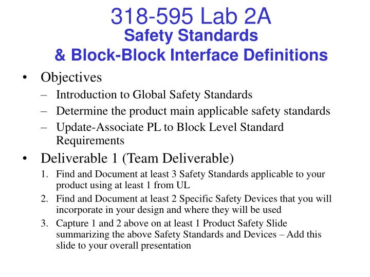
318-595 Lab 2A. Safety Standards & Block-Block Interface Definitions. Objectives Introduction to Global Safety Standards Determine the product main applicable safety standards Update-Associate PL to Block Level Standard Requirements Deliverable 1 (Team Deliverable)

E N D
318-595 Lab 2A Safety Standards& Block-Block Interface Definitions • Objectives • Introduction to Global Safety Standards • Determine the product main applicable safety standards • Update-Associate PL to Block Level Standard Requirements • Deliverable 1 (Team Deliverable) • Find and Document at least 3 Safety Standards applicable to your product using at least 1 from UL • Find and Document at least 2 Specific Safety Devices that you will incorporate in your design and where they will be used • Capture 1 and 2 above on at least 1 Product Safety Slide summarizing the above Safety Standards and Devices – Add this slide to your overall presentation
318-595 Lab 2A Block Interface Signals • Deliverable 2 – Individual Assignment for Block Owners • For Each Design Block: Define and document all of your Block-Block Interface Signals in the spreadsheet template included within the 3 main areas: • Power Signals including Power Consumed, Power Supplied • Digital Interface Signals (including busses) • Analog Interface Signals • Review ALL “Inter-block” signals and document Approval and “OK” in your spreadsheets to record signal agreements. • See attached Block Interface Signal Table Excel Tool • Summary Tab is Locked • Data Flows from Power, Digital and Analog Tabs • Some Cells have pull-down selections, Others are Free Form Values BLOCK OUTPUTS NEED TO AGREE WITH BLOCK INPUTS !!! • Deliverables for each block include: • Block Interface Excel File – Electronic • Powerpoint Summary Slide – Electronic and Paper
318-595 Lab 2A Block Signal Table: Power Power Signal Design Guidelines • Assume ALL Blocks will consume and/or provide power • Consumers must provide worst case demand to Providers (owners) • Blocks that supply power may also consume it and must allow for their inefficiencies • If you have bipolar (+/-) analog signals you will need split supplies • Power Supply Margin = ~50% • Try to keep DC voltage supplies at standard values including 3.3, 5, 9 and 12 VDC • Must specify both nominal and range of voltages • Must specify maximum total current for each voltage • Frequency range for AC voltages • Specify % regulation and max voltage ripple for DC voltages • Must specify Block-Block Interconnect Means for each signal • If a digital signal is also a power signal, treat it as a power signal
318-595 Lab 2A Block Signal Table: Digital Digital Signal Design Guidelines • A digital signal is one that conveys two levels of information (ie; 1/0, On/Off, etc) • Must classify direction from your block: Input, Output or Bidirectional • Must specify Block-Block Interconnect Means for each signal • For Inputs classify as Standard or Schmitt Trigger • Inputs must have Vih, ViL, (or Vth), Iih and IiL limits • For Outputs classify as Totem Pole, Open Collector, or Tristate • Outputs must have Voh, VoL, Ioh and IoL limits • If unsure, start by assuming Std TTL levels, Std Input, Totem Pole Output Std TTL: Vih => 2.0V, ViL <= 0.8V, Iih <= 40uA, IiL <= -1.6mA; Voh => 2.4V, VoL <= 0.4V, Ioh <= -400uA, IoL <= 16mA • For noisy or slow transition digital signals, use a Schmitt trigger input • Consider optical isolation when digital signals are needed to control or sense power electronics or high voltage electronics
318-595 Lab 2A Block Signal Table: Analog Analog Signal Design Guidelines • By default if a signal is not a Power signal, nor a Digital signal it becomes an analog signal • Classify direction of the signal with respect to the block, Input, Output or BiDir • Must specify Block-Block Interconnect Means for each signal • Classify the coupling of the signal as Direct, Capacitive, Xfmr or Other • Classify the maximum voltage (amplitude), use peak values not RMS • For input signals, classify the min-max input impedance the signal will be loaded with • For output signals, classify the min-max output impedance the signal will be driven from • Classify the min-max frequency range for the signal • Finally list any appreciable leakage current allowed for the signal if applicable
318-595 Lab 2A Block Signal Table: Summary • This tab is locked and all information flows from individual Power, Digital and Analog Tabs
318-595 Lab 2B EMC and Block Interface Signals • Objectives • Introduction to Electromagnetic Compatibility Stds • Introduction to Global AC Power and Stds • Document Applicable EMC Stds • Update your requirements at product and block level inputs to account for proper power and EMC specifications • Deliverable – Team & Individual Assignment • Update your Product Level Requirements to include all applicable EMC Stds your product should be tested to and the accompanying association to each of your Blocks – See List • Develop 1-2 slides describing overall product level EMC requirements as well as standard requirements for power inputs • Update the Excel Requirement Spreadsheet with the above and submit
318-595 Lab 2B EMC Standards Summary US/FCC:47 CFR 15 - Radio Frequency Devices 47 CFR 18 - Industrial Scientific and Medical Equipment IEC:60601-1-2 Electromagnetic compatibility - Requirements and tests 61000-3-2 EMC Part 3: Limits - Section 2: Limitation of harmonics in low-voltage supplies <16A 61000-3-3 EMC Part 3: Limits - Section 3: Limitation of voltage fluctuations and flicker in low-voltage supplies <16A 61000-3-5 EMC Part 3: Limits - Section 5: Limitation of voltage fluctuations and flicker in low-voltage supplies >16A 61000-4-1 EMC Part 4: Test/measurement techniques - Section 1: Overview of immunity tests 61000-4-2 EMC Part 4: Test/measurement techniques - Section 2: ESD immunity tests 61000-4-3 EMC Part 4: Test/measurement techniques - Section 3: Radiated radiofrequency immunity tests 61000-4-4 EMC Part 4: Test/measurement techniques - Section 4: Electrical fast transient/burst immunity tests 61000-4-5 EMC Part 4: Test/measurement techniques - Section 5: Surge immunity tests 61000-4-6 EMC Part 4: Test/measurement techniques - Section 6: Conducted radiofrequency immunity tests 61000-4-7 EMC Part 4: Test/measurement techniques - Section 7: General guide on harmonics measurement and instrum. 61000-4-8 EMC Part 4: Test/measurement techniques - Section 8: Power frequency magnetic field immunity tests 61000-4-9 EMC Part 4: Test/ measurement techniques - Section 9: Pulsed magnetic field immunity tests 61000-4-10 EMC Part 4: Test/measurement techniques - Section 10: Damped oscillatory magnetic field immunity tests 61000-4-11 EMC Part 4: Test/measurement techniques - Section 11: Voltage dips, short interruptions and variations CISPR:11 Limits and methods of measurement for Industrial, Scientific and Medical Equipment 16 Specifications for Radio Interference Measuring Apparatus and Measurement Methods 22 Limits and Methods of Measurements of Radio Interference of Information Technology Equipment For all applicable Stds, your Product Level Requirements should include Engineering Test Limits in addition to Certification Test Limits