Download
1 / 14
150 likes | 425 Views
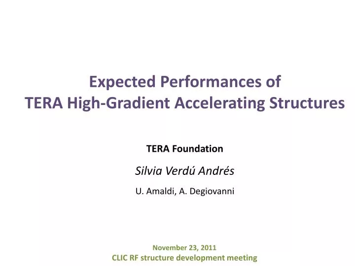
Expected Performances of TERA High- Gradient Accelerating Structures. TERA Foundation. Silvia Verdú Andrés. U. Amaldi, A. Degiovanni. November 23, 2011 CLIC RF structure development meeting. Motivation.

E N D
Expected Performances of TERA High-GradientAcceleratingStructures • TERA Foundation Silvia Verdú Andrés U. Amaldi, A. Degiovanni • November 23, 2011 • CLIC RF structure development meeting
Motivation Thehadrontherapycommunitydemands a compact, reliableacceleratorwiththeappropriatebeam performancesfortumourtreatmentwithions.
Motivation Thehadrontherapycommunitydemands a compact, reliableacceleratorwiththeappropriatebeam performancesfortumourtreatmentwithions. CABOTO is a copper standing-wave Side-Coupled Linacoperating at 5.7 GHz. Thelinaclengthcould be reducedifhighacceleratinggradients(~ 35 MV/m) wereachievedforanacceptablevalue of breakdowns(BDR ~ 10-6 bpp/m), as breakdowscompromisethe machine reliability.
Motivation Thehadrontherapycommunitydemands a compact, reliableacceleratorwiththeappropriatebeam performancesfortumourtreatmentwithions. CABOTO is a copper standing-wave Side-Coupled Linacoperating at 5.7 GHz. Thelinaclengthcould be reducedifhighacceleratinggradients(~ 35 MV/m) wereachievedforanacceptablevalue of breakdowns(BDR ~ 10-6 bpp/m), as breakdowscompromisethe machine reliability. Which are the expectedhigh gradient performances for such a machine?
Experimentalevidence • TERA 3 GHz single-cellcavity……………………………………………….… testsongoing • TERA 5.7 GHz single-cellcavity……………………………………….……… tuning • Frascati@KEK 5.7 GHz structure…..........................……………… tested! • Severalstructures at 12 and 30 GHz………………………………..……. scalinglawsbutapplicability? Frascati@KEK 5.7 GHz TERA 3 GHz *scaledto BDR = 10-6bpp/m; tp=200 ns
Structurecharacteristics TheFrascati@KEKstructureisa 5.7 GHz travelling-wave (TW)structuremade in copper. It has beendesignedtoacceleraterelativisticelectrons (Es/E0 ~ 2). Thestructurewastestedwith a 0.2 ms-long RF pulse.
Structurecharacteristics TheFrascati@KEKstructureisa 5.7 GHz travelling-wave (TW)structuremade in copper. It has beendesignedtoacceleraterelativisticelectrons (Es/E0 ~ 2). Thestructurewastestedwith a 0.2 ms-long RF pulse. CABOTO is a standing-wave (SW)structuremade in copper. It has beendesignedtoacceleratenon-relativistichadrons. Therefore, acceleratingcellspresent «noses» in ordertoimproveaccelerationbutthen Es/E0 ~ 4—5. Typical RF pulse fortherapyapplicationwould be 2 ms-long. « nose »
Structurecharacteristics TheFrascati@KEKstructureisa 5.7 GHz travelling-wave (TW)structuremade in copper. It has beendesignedtoacceleraterelativisticelectrons (Es/E0 ~ 2). Thestructurewastestedwith a 0.2 ms-long RF pulse. CABOTO is a standing-wave (SW)structuremade in copper. It has beendesignedtoacceleratenon-relativistichadrons. Therefore, acceleratingcellspresent «noses» in ordertoimproveaccelerationbutthen Es/E0 ~ 4—5. Typical RF pulse fortherapyapplicationwould be 2 ms-long. « nose » Assumptions • Applicability of results of TW to SW. • Validity of modifiedPoynting vector and associatedscalinglaws. • Validity of pulse lengthscalinglaws.
Scaling and expected performances Frascati@KEK 5.7 GHz *scaledto BDR = 10-6bpp/m; tp=200 ns
Scaling and expected performances Frascati@KEK 5.7 GHz *scaledto BDR = 10-6bpp/m; tp=200 ns
Scaling and expected performances Frascati@KEK 5.7 GHz *scaledto BDR = 10-6bpp/m; tp=200 ns Attention: Z, Sc/E0 and Rboreaffect E0, linaclength and powerrequirement!
Conclusions • Maximum achievableaverage axial field for the TERA C-band structures isaround 40 MV/m. (assumptions: • TW and SW are comparable • ModifiedPoyntingvector and associatedscalinglawsvalidity • Pulse lengthscalinglawsvalidity) • High power tests of the C-band TERA prototypes are useful to: 1) Check the validity of the scalinglaws. 2) Increase the statistics of RF high power measurementsat 5.7 GHz. [TERA] Drive the choice of the mostsuitedcellgeometry for the CABOTO-C design. • High-power test of the TERA 3 GHz single-cellcavity gains in importance: 1) Comparison of structures in S, C and X-bands. 2) Validation of modifiedPoyntingvector.
Conclusions • Maximum achievableaverage axial field for the TERA C-band structures isaround 40 MV/m. (assumptions: • TW and SW are comparable • ModifiedPoyntingvector and associatedscalinglawsvalidity • Pulse lengthscalinglawsvalidity) • High power tests of the C-band TERA prototypes are useful to: 1) Check the validity of the scalinglaws. 2) Increase the statistics of RF high power measurementsat 5.7 GHz. [TERA] Drive the choice of the mostsuitedcellgeometry for the CABOTO-C design. • High-power test of the TERA 3 GHz single-cellcavity gains in importance: 1) Comparison of structures in S, C and X-bands. 2) Validation of modifiedPoyntingvector.
Conclusions • Maximum achievableaverage axial field for the TERA C-band structures isaround 40 MV/m. (assumptions: • TW and SW are comparable • ModifiedPoyntingvector and associatedscalinglawsvalidity • Pulse lengthscalinglawsvalidity) • High power tests of the C-band TERA prototypes are useful to: 1) Check the validity of the scalinglaws. 2) Increase the statistics of RF high power measurementsat 5.7 GHz. [TERA] Drive the choice of the mostsuitedcellgeometry for the CABOTO-C design. • High-power test of the TERA 3 GHz single-cellcavity gains in importance: 1) Comparison of structures in S, C and X-bands. 2) Validation of modifiedPoyntingvector. Thanks for your attention