Download

1 / 90
900 likes | 1.03k Views
No-Code Diagnosis. A Step-by-Step Guide to Success Jim Halderman. Jim Halderman. Former flat-rate technician and instructor and a business owner. Author of many automotive books and lives in Dayton, Ohio. http://jameshalderman.com. 2. Topics to Be Discussed. Where to start diagnosis?

E N D
No-Code Diagnosis A Step-by-Step Guide to Success Jim Halderman
Jim Halderman • Former flat-rate technician and instructor and a business owner. Author of many automotive books and lives in Dayton, Ohio. • http://jameshalderman.com 2
Topics to Be Discussed • Where to start diagnosis? • Why following a procedure rather than just performing tests works best • How to look at scan tool data (PIDs) in a sequence order to reduce diagnostic time. • How to use fuel trim to diagnosis fuel delivery problems. • Many case studies as examples
Where do you start? • Step #1; Verify-If you can not verify the customer concern, you can not verify the repair • This is hard for some customers to understand. “ Don’t you believe me?” • Have the owner drive is instead of the technician • Is the troubleshooting procedure explained to the customer?
Step #2 • Visual inspection • An older technician once told me that “the vehicle will tell you what is needed” • True?
Turbo Ford Case Study(ran rough after cylinder head replacement)
Tachometer fluctuated when running • What can cause that to happen? • Bad coil? • Poor connections on coil? • Bad ignition control module? • Bad tachometer? • Poor ground?
Turbo Ford Story Conclusion • Cylinder head was not properly grounded to the block • Sealant was used on the head bolt threads • The ground from the battery was connected to the block; not the head • Spark plugs need to be properly grounded • Poor ground caused feedback to the tachometer
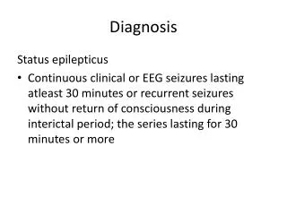
Step #3 • Check for diagnostic Trouble Codes (DTCs) • Could be performed before step #2 • Check for pending codes too • Check that all monitors have run • Could there be a driveability problem without a DTC? yes
Monitors Continuous: Misfire, Fuel System, and Comprehensive Non-Continuous: Evap., EGR, O2 Sensors, O2 Sensor Heaters, Catalyst, Heated Catalyst, A/C System, Secondary Air, and Warm-ups NOTE: In emission areas, a specific number of monitors need to be “complete” or “ready” in order to perform an emissions test.
Monitors vs. DTCs • If a monitor cannot run, then a DTC cannot be set • Always check to see if the all of the monitors have run and passed • Some require certain temperatures
Step #4 • Check for any technical service bulletins (TSBs) • Why not use the resources of many before you? • I would also suggest using www.iatn.net • Identifix
Step #5 • Check scan tool data • Look at the “high authority” sensor information
Step #6 • Narrow the problem to a cylinder or system • The systems could be the fuel, ignition or emission control system • The cylinder could be just one cylinder or a bank of cylinders
Step #7 • Find the root cause • The root cause may not be obvious but has to be found and repaired to prevent a comeback
Step #8 • Verify the repair • Use the same conditions used to verify the problem to verify the repair • Clear DTCs (not if going to an emission test????) • Write the story on the work order • The three Cs (Complaint, Cause and Correction)
Dash Warning Light On? • Check Engine • Check Engine Soon • Maintenance Required • Service Vehicle Soon • Passenger Air Bag • Trac
No-Code Diagnosis • Many times are tough to locate • Keep the basics in mind • The primary purpose of OBDII is emissions-not driveability!
2004 Prius Case Study • Poor fuel economy (25 mpg instead of normal 40+) • No codes • Scan data (PIDs) looked normal • Found right front disc brake caliper stuck. • No drop in performance noticed by the driver
7 5 6 8
Base line for Sensor Values(Except as mentioned) • Normal operating temperature (cooling fans cycled twice) • Idle (closed throttle) • All accessories off • In Park or Neutral • Closed loop
Skewed Sensors • A skewed sensor gives variable readings that appears to be accurate • However the sensor may be contaminated or dirty and sending incorrect information to the PCM • Does the PCM know the sensor is skewed?
Data Stream Step #1 • Before starting the engine, connect the scan tool. • This step is very important, especially if the driveability concern is hard starting or cold driveability.
Data Stream Step #1 (continued) • Key on/Engine off (KOEO) and look at the values for ECT (engine coolant temperature) and IAT (intake air temperature). • Basically, the same sensor and the two temperatures should agree.
ECT = IAT • The two temperatures should be the same (within 5 degrees). • Both should measure the ambient air temperature. • If the two indicate different temperatures, the one closer to the ambient air temperature is the one most likely to be correct.
ECT = IAT (continued) • The ECT sensor has a higher authority than the IAT and is therefore more likely to be the cause of a starting or cold running problem. • The ECT is the only sensor used by the PCM when the ignition key is first turned from on to start.
Quick and Easy Metric Temperature Conversion • Double the Celsius degree number • Add 25 • Should be close to the Fahrenheit temperature • Example: 50 degrees X 2= 100+25=125 • Actual= 122
Data Stream Step #2MAP= BARO • Another sensor to check is the MAP sensor because it is a high-authority sensor, especially on speed density controlled engines. • The MAP reading at KOEO should be atmospheric pressure (about 29.50 in. Hg.), depending on altitude and weather conditions. • An easier value to remember is that it should be about 4.6-4.8 volts
MAP Sensor Authority • The MAP sensor is a high-authority sensor on an engine that uses the Speed-Density method of fuel control. • If the exhaust is rich, try disconnecting the MAP sensor. • If the engine now runs OK, then the MAP sensor is skewed or giving the PCM wrong information.
MAP Too High or Too Low • The sensor could be skewed. • Check the power and ground of the sensor. • If 5-volt reference (Vref) is low, check other sensors that also use the reference voltage.
Data Stream Step #3IAC Counts • After the engine starts, observe the IAC counts or percentage. • The IAC is used to control idle speed by changing the amount of air bypassing the throttle plate (just like depressing or releasing the throttle pedal).
IAC (continued) • On a warm engine (cooling fans cycled twice), the IAC counts should be 15-25 counts or percentage. • If the IAC commanded position is low, a vacuum leak (speed density engines mostly) could be indicated. • The extra air decreases the vacuum and the MAP sensor reads this drop as an increase in load. The PCM adds fuel, increasing the engine speed.
IAC Too High • If the IAC position is higher than normal. This could indicate a dirty throttle plate(s) or a vacuum leak on a MAF engine.