Download
1 / 20
210 likes | 485 Views
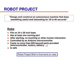
Department of Electrical Engineering. The Bioloid Robot Project. Supervisor: Ido Cohen. Presenters: Michael Gouzenfeld Alexey Serafimov. Winter 2012-2013. The project’s goal. Making the robot independently approach to a ball and kick it. The project’s main tasks.

E N D
Department of Electrical Engineering The BioloidRobotProject Supervisor: Ido Cohen Presenters: Michael Gouzenfeld Alexey Serafimov Winter 2012-2013
The project’s goal Making the robot independently approach to a ball and kick it
The project’s main tasks • Creating an API for embedded robot’s controller in C, which will allow controlling the robot on higher level • Creating an image processing mechanism for the robot’s camera in C++ • Creating a protocol for communication between the image processing unit on PC and the robot • Creating the decision making controller – the “brain”
The Bioloid Robot(Premium Upgrade Kit ++) 2-Axis Accelerometer Robotis Wireless CMOS Camera 230x240, 30 FPS CM-510 controller based on Atmel ATmega1281 8-bit AVR microcontroller DMS – Distance Measurement Sensor (IR) Dynamixel AX-12 motorx 20 ZigBee Zig-110 Wireless Module
The general idea Peripheral Devices The Controller PC The Robot Image Processing Unit Camera Receiver USB Camera Sensors Main Controller Motion Controller Wireless Data Processing Unit UART ZigBee ZigBee Dynamixels Wireless connection
Motion Controller structure Motion control Indicators Head Robot’s body movement management Body Robot’s body movement management Buzzer Robot’s sound management Main All modules initialization The main procedure LEDs Robot’s CM-510 LEDs handling Motion Dynamixels management SW Utilities Memory ATmega1281 memory management Sensors Communication ADC Analog port data processing DMS Robot’s distance measurement data processing ZigBee Wireless communication controller Errors Failures handling Buttons Robot’s CM-510 buttons handling Accelerometer Accelerometer data processing Utilities General helper functions
Motion control Terminology • Dynamixel’s Offset – a dynamixel’s absolute angle • Dynamixel’s Speed– a dynamixel’s speed of rotating
Motion control Terminology • Pose – a set of dynamixels’ offsets (except for the head) • Page – a set of poses to be played sequentially Except for the poses, page also holds an information about: play time, delays, next page to play etc.
Motion control Terminology • Memory program space – the memory space, where the code resides • Memory data space – the memory space, where the data resides The user can’t access the program space directly due to AVR processor’s Harvard architecture, but using special functions
Motion control Terminology • Robot’s Head – the robot’s head is an add-on of 2 dynamixels and a camera to the original Premium Upgrade Kit The head has 2 degrees of freedom: tilt and pan
Motion control Memory management • To avoid spending time on teaching the robot new poses, the poses provided by manufacturer are used • The manufacturer (ROBOTIS) places all the motion data in the program space • Original pages of poses are copied from program space to data space • The data space is to small to hold all the pages, so a sort of caching mechanism was implemented, based on the random replacing policy
Motion control Pose playing • The challenge is setting the robot’s pose, such as all the dynamixels will start and end their motion simultaneously. • This is performed by the next means: • Calculating the correct speed for each dynamixel to move with, according to the offset to be performed. • Sending a broadcast message on the Dynamixel’s bus, such as all off it get the moving command at the same time
Motion control Page playing • When playing a page of poses, there are defined speeds and delays for each pose, so the dynamixel’s speeds are adjusted accordingly • After reaching the end of page, there is a jump to the Next Page (one of the page’s properties). • Also there is a Stop Page pointer to jump there if something’s wrong
Motion control Motion cycle ZigBee command arrived? No Play the initial pose Yes What kind of command? Move head Preload relevant pages into the cache Body Head Management Any sensors changed? No Yes Perform management operations such as: update default dynamixels offsets Correct the pose(s) Play the pose(s)
Motion control Motion cycle • Some explanations to the previous slide: • During the motion play, the sensors are sampled and some corrections to the motion can be made. For example: • If accelerometer detects falling, the appropriate dynamixels are moved to avoid it • If DMS detects close object while walking, the robot will try to avoid the obstacle by walking around it • If a button is pressed, robot returns to its initial pose • As a result of ZigBee command the relevant page sequence is being played, but after each pose there is a check if the ZigBee command has changed, so another sequence will be played
Image processingGeneral principles • The general principles of the tracking: • Choosing the object’s color, which should be different from the background color • The image processor calculates the average geometrical location of the chosen color on the screen. • The command to move robot’s head is sent to the robot, such as the average geometrical location will be at the center of the screen (in infinite loop).
Wireless communicationGeneral principles • Wireless communication between Main Controller and robot is performed using ZigBee protocol (not talking about video data, only the commands) • The commands are generated (and can be received) by the Wireless Data Processing unit and are sent to the robot. • With correct ZigBee devices configuration the command generation from RC-100 (remote controller) is also supported
Main Controller (not implemented yet )General principles • The Main Controller is responsible for making a decision about a command to be sent to the robot according to results received from the Image Processing unit. • The Image Processing unit provides the Main Controller with data about the object’s (ball) location, such as: • The relative angle in horizontal plane • Estimated distance • The Main Controller sends the movement commands to the robot • The above actions are done in the loop until the robot finally is in the ball-kick position • The kick command is sent
Future development possible directions • Placing the main controller on the robot (some lite weight, but strong computing device), to make the robot completely independent • Upgrading the accelerometers (called “gyro” by the manufacturer) with the real gyros, to improve robot’s stability (falling prevention) • Improving the motion algorithms and flows by the principle: • Efficiency in cost of modularity • Upgrading the camera for better performance • Improving image processing for new features to be possible, such as: • Easy obstacle overcoming instead of avoiding • Adding some device to the robot, which will allow: • Navigation • Shortest path finding • ...