Download
1 / 67
780 likes | 1.23k Views
New Comprehensive Equation to Predict Liquid Loading . Shu Luo The University of Tulsa. Outline. Introduction Background and Approach Model Formulation Model Validation Program Demonstration Summary. What is liquid loading?. Minimum pressure drop in the tubing is reached

E N D
New Comprehensive Equation to Predict Liquid Loading ShuLuo The University of Tulsa
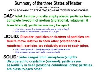
Outline • Introduction • Background and Approach • Model Formulation • Model Validation • Program Demonstration • Summary
What is liquid loading? • Minimum pressure drop in the tubing is reached • The liquid drops cannot be entrained by the gas phase (Turner et al.) • The liquid film cannot be entrained by the gas phase (Zhang et al., Barnea) • The answers from different definitions are not the same
Traditional Definition IPR Stable OPR Unstable Transition Point Liquid Loading
Traditional Definition • As gas flow rate increases • and • At low velocities decreases faster than increase in • When two gradients are equal, minimum occurs
Definition based on Mechanisms • Two potential mechanisms of transition from annular to slug flow • Droplet reversal • Film Reversal • Models are either based on droplet reversal (Turner) or film reversal (Barnea)
Air-Water Flow • Anton Skopich conducted experiments in 2” and 4” pipes • The results observed are different based on film reversal and minimum pressure drop
Calculation Procedure • Total pressure drop is measured and gradient is calculated • Holdup is measured and gravitational gradient is calculated • Subtracting gravitational pressure gradient from total pressure gradient to get frictional pressure gradient • By dividing the incremental pressure gradient by incremental gas velocity, changes in gravitational and frictional gradients with respect to gas velocity are calculated.
Magnitude of Gravitational vs. Frictional Gradient with respect to Gas Velocity
Total dp/dzAir-Water, 2 inch, vsl=0.01 m/s Film Reversal
dP/dz)Gvs. dP/dz)FAir-Water, 2 inch, vsl=0.01 m/s dp/dz)F is zero
dP/dz)G vs. dP/dz)FData from Netherlands (2 inch) dp/dz)F is zero
dP/dz)G vs. dP/dz)F TUFFP (3 inch, vsl=0.01 m/s) dp/dz)F is zero
dP/dz)G vs. dP/dz)F TUFFP (3 inch, vsl=0.1 m/s) dp/dz)F is zero
Total dp/dzAir-Water, 4 inch, vsl=0.01 m/s Film Reversal
dP/dz)G vs. dP/dz)FAir-Water, 4 inch, vsl=0.01 m/s dp/dz)F is zero Film reversal
Liquid Loading Definition • Liquid loading starts when liquid film reversal occurs • We adopt the model of film reversal to predict inception of liquid loading • The reason for this adoption, as we will show later, is because we are able to better predict liquid loading for field data using this methodology.
Outline • Introduction • Background and Approach • Model Formulation • Model Validation • Program Demonstration • Summary
BackgroundTurner’s Equation • The inception of liquid loading is related to the minimum gas velocity to lift the largest liquid droplet in the gas stream. • Turner et al.’s Equation: • This equation is adjusted upward by approximately 20 percent from his original equation in order to match his data.
Background Drawbacks with Turner’s equation • Turner’s equation is not applicable to all field data. Coleman et al. proposed equation (without 20% adjustment ) • Veeken found out that Turner’s results underestimate critical gas velocity by an average 40% for large well bores. • Droplet size assumed in Turner’s equation is unrealistic based on the observations from lab experiments. • Turner’s equation is independent of inclination angle which is found to have great impact on liquid loading.
ApproachFilm Model • Two film models are investigated to predict liquid loading: • Zhang et al.’s model(2003) is developed based on slug dynamics. • Barnea’s model(1986) predicts the transition from annular to slug flow by analyzing interfacial shear stress change in the liquid film.
ApproachZhang et al.’s Model • Momentum equation for annular flow: • With other equations and closure relationships, we can solve this momentum equation and calculate critical gas velocity
ApproachBarnea’s Model • Constructing force balance for annular flow and predict the transition from annular to slug flow by analyzing interfacial shear stress changes. • The combined momentum equation: • Interfacial shear stress from Wallis correlation: Schematic of Annular Flow
ApproachBarnea’s Model • Solid curves represent Interfacial shear stress from combined momentum equation • Broken curves represent Interfacial shear stress from Wallis correlation • Intersection of solid and broken curves yields a steady state solution of film thickness and gas velocity at transition boundary • Another transition mechanism is liquid blocking of the gas core. Transition
Outline • Introduction • Background and Approach • Model Formulation • Model Validation • Program Demonstration • Summary
Three Main Modifications • Accounted for variable liquid film thickness • Changed the equation for liquid film friction factor • Accounted for presence of liquid in the form of droplet
Model Formulation • In inclined wells, the film thickness is expected to vary with radial angle Vertical Well Inclined Well
Non-uniform Film Thickness Model • Let A1=A2, we can find this relationship. • If film thickness reaches maximum at 30 degree inclination angle
Non-uniform Film Thickness Model • We will use the following film thickness equation in the new model:
Non-uniform Film Thickness Model • Only maximum film thickness will be used in the model because thickest film will be the first to fall back if liquid loading starts. • Find critical film thickness δTby differentiating momentum equation. δT equals to maximum film thickness δ(π,30).
Interfacial Friction Factor • Critical gas velocity calculated by Barnea’s model is conservative compared to other methods. Fore et al. showed that Wallis correlation is reasonable for small values of film thickness and is not suitable for larger film thickness liquid film. • A new correlation is used in the new model :
Outline • Introduction • Background and Approach • Model Formulation • Model Validation • Program Demonstration • Summary
Turner’s Data • 106 gas wells are reported in his paper, all of the gas wells are vertical wells. • 37 wells are loaded up and 53 wells are unloaded. 16 wells are reported questionable in the paper. • Current flow rate and liquid loading status of gas well are reported.
Turner’s Model ResultsTurner’s Data Vg < Vg,c Vg > Vg,c
Coleman’s Data • 56 gas wells are reported, all of the wells are also vertical wells. • These wells produce at low reservoir pressure and at well head pressures below 500 psi. • Coleman reported gas velocity after they observed liquid loading in gas wells.
Veeken’s Data • Veeken reported offshore wells with larger tubing size. • 67 wells, which include both vertical and inclined wells, are presented. • Similar to Coleman’s data, critical gas rate was reported. • Liquid rate were not reported in the paper. We assumed a water rate of 5 STB/MMSCF.