Download
1 / 26
260 likes | 435 Views
Markov Modeling of the Channel for HEW System Level Simulations. Authors:. Date: 2013-09-17. Abstract.

E N D
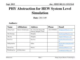
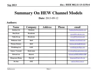
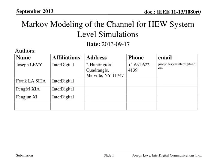
Markov Modeling of the Channel for HEW System Level Simulations Authors: • Date:2013-09-17 Joseph Levy, InterDigital Communications Inc..
Abstract • This contribution proposes that a Markov Model be used in system level simulations to provide an accurate and efficient means of including fast fading of outdoor channels for HEW system level modelling. Similar methods have been used by 3GPP for LTE modelling and 802.16 for 802.16e modelling. Joseph Levy, InterDigital Communications Inc..
Motivation • To provide an accurate and efficient outdoor physical channel model for HEW system level simulations. • Markov modeling techniques can provide such a system level simulation model. ([2], [5], [10]) • The Markov modeling technique can be used for any agreed channel model (e.g. WINNER2, ITU, or customized) • The modeling approach and channel model(s) used for system level simulations are important considerations which should be agreed to allow for meaningful comparison of performance results. (10^5) (10^5) Joseph Levy, InterDigital Communications Inc..
Discussion • This contribution provides: • A description of the proposed Finite State Markov Chain (FSMC) system level modeling • Examples of calculated transition probability matrix (TPM) for some channel models of interest. (10^5) Joseph Levy, InterDigital Communications Inc..
Joseph Levy, InterDigital Communications Inc.. Description of the proposed Finite State Markov Chain (FSMC) system level modeling
Finite State Markov Chain • Model the channel SNR as a finite-state Markov chain (FSMC) • Each state represents a given value (range) of the SNR • The following example has four different SNR states Joseph Levy, InterDigital Communications Inc..
Use of FSMC in System Level Simulations Joseph Levy, InterDigital Communications Inc..
Transition Probability Matrix (TPM) • Transition probability matrix • pi,j : prob that the jth state is next, given that the ith state is current • be the prob distribution function when current state is the ith state • The underlying physical channel is fully characterized by the corresponding TPM matrix. Joseph Levy, InterDigital Communications Inc..
Multi-Carrier SNR Mapping • In modeling the physical channels, we need to convert multiple SNR values (one per subcarrier) into one single SNR value • Potential approaches • Throughput averaging (algo 1) • Straightforward, not MCS dependent • effective channel amplitude square • SNR averaging (algo 2) • Used by OPNET for LTE downlink/uplink • Exponential effective SNR mapping (EESM), received bit mutual information (RBIR), Mean mutual information per bit (MMIB) [10] • MCS dependent (not studied herein) Joseph Levy, InterDigital Communications Inc..
Joseph Levy, InterDigital Communications Inc.. Examples of calculated transition probability matrix (TPM) for some channel models of interest.
Proposed HEW Use Cases [9] Joseph Levy, InterDigital Communications Inc..
Urban Micro Channels in HEW • Urban Micro cellular environment fits well in HEW [8] • “The microcellular test environment focuses on small cells and high user densities and traffic loads in city centers and dense urban areas. The key characteristics of this test environment are high traffic loads, outdoor and outdoor-to-indoor coverage. This scenario will therefore be interference-limited, using micro cells.” [7] WINNER 2 model • Metropolitan (C2) • Typical Urban (B1, B4) • Indoor to outdoor (A2) • Rural macro (D1) • ITU model • Urban macro (UMa) • Urban micro (UMi) • Indoor (InH) • High speed (RMa) Joseph Levy, InterDigital Communications Inc..
TPM Generation Algorithm • Generate multiple (10^5) pairs of channel samples, each pair are separated by N OFDM symbols (N * 3.2 ms) • Each consists of multiple taps according to the channel model, e.g. WINNER 2 or ITU • Will serve as current state and next state in statistics collection • For each sample in the channel sample pair, • Convert it to freq domain using DFT • Convert multiple subcarrier SNRs into one effective SNR (either SNR averaging or throughput averaging) • Quantize the effective SNRs into P (16) equi-prob states • Find the probability of each state transitioning into other states accordingly Joseph Levy, InterDigital Communications Inc..
Simulation Assumptions • Channel Scenarios: WINNER 2 B1, ITU UMi • Directly comparable channel scenarios • Single transmit and single receive antenna • OFDM symbol separation between current and next state: 10 or 100 • Large scale signal to noise ratio: 0 or 20dB • Mobile velocity: 3 or 30 km/hr • Two algorithms considered for determination of effective SNR: • Throughput averaging • SNR averaging Joseph Levy, InterDigital Communications Inc..
ITU/WINNER 2 Comparison, 100 symbols. 20dB SNR, 30 km/h, Throughput Averaging • The generated TPM are more or less similar for WINNER 2 B1 and ITU UMi Joseph Levy, InterDigital Communications Inc..
ITU/WINNER 2 Comparison, 100 symbols. 20dB SNR, 30 km/h, SNR Averaging • The generated TPM are more or less similar for WINNER 2 B1 and ITU UMi Joseph Levy, InterDigital Communications Inc..
SNR Comparison, 20dB vs. 0dB, 100 symbols, 30 km/h, WINNER 2 B1 Throughput Averaging • Large scale SNR does not change the TPM noticeably (throughput averaging) Joseph Levy, InterDigital Communications Inc..
Discussion on Multi-Carrier SNR Mapping • SNR averaging • Simple, independent of large scale SNR • SNR averaging occurs in the linear domain • Throughput averaging • Strictly speaking depending on large scale SNR • This dependence is weak though (see comparison on previous page) and may be removed for simplicity • The mapping may thus be approximated by SNR averaging in the dB domain Throughput averaging SNR averaging in the dB domain Joseph Levy, InterDigital Communications Inc..
Simulation Summary • Markov modeling of PHY multipath channels in HEW • TPM more or less similar for ITU UMi and WINNER 2 B1 channel • Faster velocity leads to more state changes in TPM • Larger separation leads to more state changes in TPM • Converting multiple subcarrier SNRs into a single value • SNR averaging in the linear domain • Throughput averaging • may be approximated by SNR averaging in the dB domain • More complex averaging may be used • The general method may be applied to any other indoor or outdoor channels for HEW system level simulations • ITU channels • WINNER 2 channels • and others Joseph Levy, InterDigital Communications Inc..
Potential Items of Agreement • Use of Markov modeling of PHY multipath channels • Channel model(s) to be used (e.g. ITU UMi and WINNER 2 B1) • Velocities to be considered • SNR to be considered • Number of Symbols to be averaged • Method of converting multiple subcarrier SNR • Throughput averaging • More complex averaging • TPM for each agreed configuration • Generate multiple (e.g. 10^5) pairs, number of symbols separating pairs, N • Number of equi-probable states, P (e.g. 16) Joseph Levy, InterDigital Communications Inc..
References • [1] IEEE 802.11-13/0722r1, “HEW SG Evaluation Methodology”, Intel. • [2] IEEE 802.11-04/0184r0, “802.11n TGn proposal for PHY abstraction in MAC simulators,” ST Microelectronics. • [3] R. Yaniv et. Al., “CINR measurements using the EESM method”, IEEE C802.16e-05/141r3. • [4] L. Hentilä, P. Kyösti, M. Käske, M. Narandzic , and M. Alatossava. (2007, December.) MATLAB implementation of the WINNER Phase II Channel Model ver1.1 [Online]. Available: https://www.ist-winner.org/phase_2_model.html • [5] OPNET Technologies Inc., “LTE PHY Multipath Fading Models – Design Document”. • [6] Software implementation of IMT.EVAL channel model, doc num: IST-4-027756 • [7] Report ITU-R M.2135-1 (12/2009) Guidelines for evaluation of radio interface technologies for IMT Advanced • [8] IEEE 802.11-13/0996r1, . “Outdoor Channel Model Candidates for HEW”, K. Josiam, R. Taori, and F. Tong, • [9] IEEE 802.11-13/0657, “Usage models for IEEE 802.11 High Efficiency WLAN study group (HEW SG) – Liaison with WFA”, Laurent Cariou • [10] IEEE 802.16m-08/004r5, “IEEE 802 16m Evaluation Methodology Document (EMD)” Joseph Levy, InterDigital Communications Inc..
Joseph Levy, InterDigital Communications Inc.. Additional TPM plots
Velocity Comparison, 30 km/h vs. 3 km/h, 100 symbols, 20dB, WINNER 2 B1 Throughput Averaging • Faster velocity leads to more state transitions Joseph Levy, InterDigital Communications Inc..
Packet Duration Comparison, 10 vs. 100 symbols, 20dB, 30 km/h, WINNER 2 B1 Throughput Averaging • Larger separation leads to more state transitions Joseph Levy, InterDigital Communications Inc..
Algorithm Comparison,100 symbols, 20dB, 30 km/h, WINNER 2 B1 Joseph Levy, InterDigital Communications Inc..
Algorithm Comparison,100 symbols, 20dB, 30 km/h, ITU Channel UMi Joseph Levy, InterDigital Communications Inc..