Download
1 / 23
260 likes | 417 Views
Beam-Based Alignment Results. Henrik Loos, for the LCLS Commissioning Team. Undulator Trajectory Requirements. Beam through undulator rms 2 μ m per gain length Undulator with 33 segments total 100 m Not possible with conventional alignment

E N D
Beam-Based Alignment Results Henrik Loos, for the LCLS Commissioning Team
Undulator Trajectory Requirements • Beam through undulator rms 2 μm per gain length • Undulator with 33 segments total 100 m • Not possible with conventional alignment • Use beam based alignment using set of different energies • RF BPM resolution < 1 μm
Undulator Configuration In/Out BFW Undulator Quad Corr RF BPM K Beam Scan Girder Girder Movers • Undulator, Quad, BPM, BFW move with girder • Beam Finder Wire (BFW) retractable • Horizontal translation of undulator • Complete retract (80 mm) • Undulator K adjustment (± 5 mm)
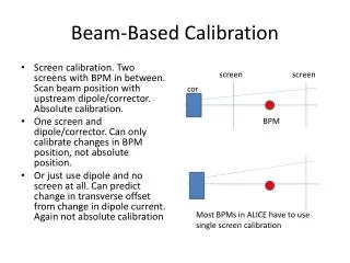
Beam Based Alignment Principle • BPM offsets unknown • Magnetic fields (earth, quad kicks, etc.) unknown • Correct field integrals with quad offsets or correctors for dispersion free trajectory at BPM position • Trajectory between BPMs remains unknown • Measure trajectory at different energies to extrapolate to straight line at infinite energy • Fixed undulator quad fields • BPM position is BPM offset at infinite energy
BBA Measurement Schematic Δb0 Δb1 Δb2 Δb3 Δb0 Δq1 Δq2 Δq3 E2 x,x’ E1 Δy0 Δy1 Δy2 Δy3 Δy4 BPM Offsets Δbi Quad Offsets Δqi E1<E2
BBA Procedure • Model beam position (yj) at BPMs as function of initial launch at 1st BPM (xi), quad offsets (Δqi), BPM offsets (Δbi) • y = [RxRqRb] [x’Δq’Δb’]’ • Rxj = Rj1,1:2 • Rqj = [R1,jend- R1jbeg … Ri<j,jend- Ri<j,j 0 … 0]11 • Rb = -I • Fit solution for y arbitrary to adding linear function to quad and BPM offsets • Add constraint equations for quad or BPM offsets • 0 = ΣiΔqi and ΣiziΔqi for linear quad offset constraint • 0 = Δqi for minimum quad offset constraint
BBA Implementation • Setup accelerator for one energy • Calculate response matrix for this energy • Measure N orbits at this energy and average • Repeat for all energies • Generate final matrix with separate launch parameters for each energy and selected constraints • Fit quad and BPM offsets and implement • Repeat BBA procedure
BBA Simulation Simulation Orbits Simulation Fit Lin. Quad
BBA Results: 1st Run • First test: Energy range only 10 – 13.64 GeV • 50 orbits each, averaged • BPMs not well calibrated • Large oscillation in fit of quad offset, 1mm error bar • Assume BPM offset worse than quad offset • Apply instead constraint for minimal quad offset • Initial position rms 300 μm Measured Orbit
BBA Results: 1st Run Fit with Linear Quad Constraint Fit with Min. Quad Constraint Applied this to BPM offsets
BBA Results: 2nd Run • Energy range now 7 – 13.64 GeV • Still large ~1 mm oscillation on quad offset fit • Apply relaxed minimum quad constraint, 100 μm error bar • Orbits very similar after correction • Position rms ~50 μm after Measured Orbit
BBA Results: 2nd Run Fit with Min Quad Scale 20 Measured Orbit after Correction
BBA Results: 3rd Run Measured Orbit 4.3 – 13.64 GeV Fit with Linear Quad Constraint
BBA Results: 3rd Run Measured Orbit 4th Iteration Fit with Linear Quad Constraint Position rms 2 – 10 μm Offset Error Bar 10 μm
BBA Results: Best Orbit • Carefully calibrated BPMs • Energy range 4.3 – 13.64 GeV • 4 different energies • Undulator launch feedback on • Average position rms 1 – 2 μm • Betatron jitter ~20 μm
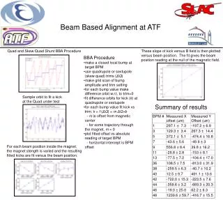
BBA Results: Girder Bump Test 58um bump @ 13.7 GeV & -58um BPM offset -48um bump @ 13.7 GeV BBA procedure finds both quad offsets and BPM offsets
Typical BBA After Several Months Observe mostly changes in BPM offsets ~ 10 – 30um Some quad & BPM offsets in end region of undulator from incremental orbit corrections (retracting undulators, changing of taper)
Quad Alignment Measurement Earth’s field effect 8 mm rms undulators installed (with m-metal) Measure quadrupole offset from beam axis Vary quad magnetic field and fit offset to trajectory kick Verifies earth field compensation from BBA Z (m) P. Emma
BBA User Interface Fit Options Simulation Measurement Corrections
Fast Linac Energy Change • User interface to run an automated script • Block/unblock beam • Activate saved klystron configuration • Trim saved magnet configuration • Toggles feedbacks • Enables one BBA run in 10 - 15min (at best), ~2 – 4 h (worst)
BBA & Undulator Taper • Orbit effects from undulator motion • No earth field shielding with retracted undulator • Undulator translation (~80 mm) shifts entire girder by ~10 - 100 um (quad & BPM) • Undulator field integral depends on taper • Goal • Straight trajectory for all undulator translations • Strategy • Do BBA at design taper, correct quad position • Compensate field integral change for different taper with corrector coil • Compensate girder shift for retracted undulator with corrector coils and BPM offset
Undulator Field Integral Measurement Apply 1st field integral to corrector coil
Summary • Achieved • BBA procedure successfully implemented • Converges to ~1 μm trajectory rms • Important to have full energy range • Errors on fitted quad offsets decreased from 1 mm to 10 μm with increasing energy range • Fast energy switching 15 min BBA possible • Complemented by measurement of quad offsets by varying quad strength • To Do • Fully automate energy change (Interface to energy management, orbit feedback in linac) • Study BBA at low charge (< 250 pC) • Implement orbit correction from undulator translation • Compare girder position from BBA with alignment diagnostic system (ADS) • Monitor and study BPM offset drifts