Download
1 / 19
210 likes | 463 Views
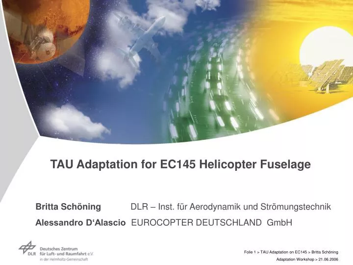
TAU Adaptation for EC145 Helicopter Fuselage. Britta Schöning DLR – Inst. für Aerodynamik und Strömungstechnik Alessandro D‘Alascio EUROCOPTER DEUTSCHLAND GmbH. Overview. Introduction Geometries EC145 and BK117-C2 Grid generation Calculation parameters CFD results

E N D
TAU Adaptation for EC145 Helicopter Fuselage Britta Schöning DLR – Inst. für Aerodynamik und Strömungstechnik Alessandro D‘Alascio EUROCOPTER DEUTSCHLAND GmbH
Overview • Introduction • Geometries EC145 and BK117-C2 • Grid generation • Calculation parameters • CFD results • Forces and moments (FLOWer/TAU/Experiment) • Pressure and skin friction lines (FLOWer/TAU) • TAU adaptation • Conclusion
IntroductionBackground and Objective • Unsteady RANS equations have reached a high degree of accuracy for moderate detached flows (like on airplanes). The blunt body of the EC145 helicopter is caused by its missions. Because of the high curvature in the area of the back door we can expect massive separations for which aerodynamic simulation tools are necessary. • Objective of the work was • to investigate the effect of turbulence models in high separation areas on particularly complex helicopter fuselage such as the EC145 • investigation of TAU adaptation capability • comparison FLOWer / TAU
GeometryCFD model:EC145 CAD model CAD model CFD model CATIA V4 • Simplifying the geometry • Repairing the surface patches • Closing of air intakes and jet exhausts
GeometriesComparison:EC145 (CFD model) BK117-C2 (experimental model) stabilizers EC145 BK117-C2 conical junction air inlets - cabin roof back door area
Grid GenerationHybrid Grid Generation by Centaur TAU • 88697 surface points • 25 prism layers (without chopping) • 3.7106 points pre-refined mesh
Grid generationStructured Grid Generation by ICEM Hexa FLOWer Volume grid C-O topology 64 blocks 80968 surface points 4.9 Mio. points
CFD Code DLR TAU/FLOWer Finite Volume Solver for 3D RANS Equations • M = 0.117 • α = -18°, -12°, -6°, 0°, +6°, +12° • Re = 2.7·106 • Multi-grid: 3v cycle • Steady calculation on Linux-Cluster (16 processors)
TAU: SST k-ω 2. adaptation BK117-C2 Experiment FLOWer: RSM FLOWer: SST k-ω TAU: Wilcox k-ω TAU: SST k-ω CFD results Forces and Moments cL Lift coefficient cm cD Drag coefficient Pitching moment a [] a []
CFD Results Skin Friction Lines TAU FLOWer 2-equation SST k- ω turbulence model 2-equation Wilcox k- ω turbulence model 2-equation SST k- ωturbulence model 7-equation RSM turbulence model
CFD Results Pressure Coefficient • Cut plane y = 0 [mm]
CFD Results Total Pressure Losses • Cut plane y = 0 • α = 0° FLOWer – SST k-ω model TAU – Wilcox k-ω model FLOWer – RSM model TAU – SST k-ω model
4.9106 points 3.7106 points CFD Results Prediction of Wake Total Pressure Losses α = 0° TAU without adaptation
TAU Adaptation (1) • Pre-refined mesh: sufficient to predict total forces and moments • Goal: TAU adaptation to improve local field phenomena and interaction with tail • Adaptation variable: Total pressure losses • Two adaptation steps • Number of points: start grid 3.7Mio points grid of 1st adaptation 4.3Mio points (+16%) grid of 2nd adaptation 5.1Mio points (+18%) • Additional parameters: - minimum edge length - no cut out boxes - 2nd adaptation with re- and de-refinement approach • Adaptation of the SST turbulence model results
TAU Adaptation (2) Start grid 1. adaptation 2. adaptation
TAU Adaptation (3) Wake, total pressure losses, y = 0, α = 0° Calculation on initial grid Calculation on 1. adaptation border of pre-refinement Calculation on 2. adaptation
CFD Results Pressure Coefficient • Cut plane y = 0 [mm]
TAU Adaptation (4) Wake, total pressure losses, α = 0° Calculation on initial grid Calculation on 2. adaptation
Conclusion, Outlook • The comparison of forces and moments between the solvers FLOWer and TAU and the experimental data show a good agreement without TAU adaptation but with a pre-refined grid. • TAU adaptation improvesresolution of local flow phenomena, necessary to be compatible with structured meshes (FLOWer). Future plans: • Further work planned in SHANEL to qualify adaptation capability forhelicopter applications (BVI, helicopter wakes).