Download
1 / 26
260 likes | 443 Views
MPLS ADAPTIVE TRAFFIC ENGINEERING. Anwar Elwalid Debasis Mitra K. G. Ramakrishnan Mathematical Sciences Research Center Bell Laboratories Lucent Technologies Murray Hill, New Jersey USA. Agenda. Traffic Engineering over MPLS Design of Label Switched Paths (LSPs)

E N D
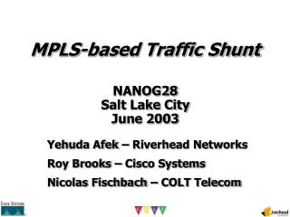
MPLS ADAPTIVE TRAFFIC ENGINEERING Anwar Elwalid Debasis Mitra K. G. Ramakrishnan Mathematical Sciences Research Center Bell Laboratories Lucent Technologies Murray Hill, New Jersey USA
Agenda • Traffic Engineering over MPLS • Design of Label Switched Paths (LSPs) • Distributed Optimization with Lucent’s VNN • Global Centralized Optimization • Online Adaptive Traffic Engineering on LSPs • MATE (MPLS Adaptive Traffic Engineering) • Stability and Performance Issues
LSP LDP is used to build the LSPs, using IP forwarding tables to follow the paths used by hop-by-hop routing Label Switched PathsThat Follow Routing MPLS Domain Core LSRs Egress LSR Ingress LSR Congested link Uncongested link
MPLS Explicit Routing MPLS Domain Core LSRs LSP 1 Egress LSR Ingress LSR LSP 2 LSP 3 Multiple explicitly routed Label-Switched Paths (LSPs) between an ingress-egress pair can be efficiently established
VNN: Lucent’s Constraint-Based Routing Contributor: Andrew Malis • Pioneered by Cascade/Ascend/Lucent • Enhanced OSPF • Extra LSA types (for trunks and other addressing plans) • Extra metrics (discussed on next slide) • modified routing calculations • Proprietary source-based signaling to set up explicit paths calculated by enhanced OSPF • Multi-service: • LSPs for IP Navigator MPLS • ATM circuits • Frame relay circuits
Accumulative metrics: Administrative cost Delay Cell delay variation Hop count Qualifying constraints: Bandwidth per QoS class (ATM Forum) per priority level in 10% increments Cell Loss Ratio VPN ID Link type cell/frame Congestion state Routing Metrics and Constraints
Path Calculations • In general, calculations involving multiple constraints are NP-complete • VNN routing calculation: • Discard links unable to deliver desired service levels, by examining qualifying metrics • Shortest path calculation optimizing any one of the “accumulating metrics” • Sample paths: • Path to node X having 100 Kbps free bandwidth, and optimizing administrative cost. • Point-to-multipoint path for VPN 22, having QoS class of ABR and a MCR of 6000 cells/second.
VNN Signaling • Explicit path setup • Fully distributed • Crankback to signaling source, when routing advertisements and actual link parameters differ • Automatic reroute on link failure • Paths reestablished even if insufficient resources • Load balancing, or reroute of established LSPs • To make use of newly provisioned trunks • Configurable per-source • Only when existing LSP has insufficient resources, or there is a cheaper path
Other LSP/VC Routing Functions • Routing protocol indicates when circuits must be rerouted around failures • Routing protocol carries congestion indications to network edge, where policies parameters can be changed • Routing protocol distributes link resource data to where calculations can be done most easily • Announces entry of new nodes or links to the network
Global Optimization-Based LSP Design • Lucent Research (D. Mitra, K. G. Ramakrishnan), “A case study of Multiservice, Multipriority Traffic Engineering Design”, GLOBECOM ‘99 (http://cm.bell-labs.com/~mitra) • Given: • Network topology, link bandwidth and delay • Batch of QoS demands (source, destination, bandwidth, e2e delay) and Best Effort demands (source, destination, bandwidth) • Additional sharing constraints between QoS and Best Effort • Goal: LSP specification (route, size) which maximizes weighted measure of carried demands (“revenue”) subject to QoS requirements. • Standard Global Optimization: Computationally intractable • New Approach: Multi-step decomposition approach
Step 1: Generation of set of all candidate routes which satisfy end-to-end delay requirements of QoS demands • polynomial time algorithm • Step 2: Global optimization of LSP design for QoS demands subject to route set from step 1. • maximizes revenue; route-based Linear Program • Step 3: Global optimization of LSP redesign for QoS demands to minimize resource usage subject to identical revenue from step 2 • also route-based LP • Step 4: Global optimization for LSP design for Best Effort demands on residual network from step 3 • edge-based multicommodity flow; rich route diversity
MATE: MPLS Adaptive Traffic Engineering • <draft-widjaja-mpls-mate-01.txt> • Ongoing Research: A. Elwalid, C. Jin, S. Low, I. Widjaja • Features of MATE: • Adaptive traffic mapping onto LSPs to minimize congestion • End-to-end control with no new hardware or protocol requirements at intermediate LSRs • No knowledge of a priori traffic distribution is required, and no particular scheduling or buffering schemes are assumed • Traffic Engineering at different granularities • Minimal packet re-sequencing
Incoming Packets MATE Functions in Ingress LSRs LSPs (FEQ) Measurement and Analysis Probe Packets LSP1(FEQ) LSP2(FEQ) Filtering and Distribution Traffic Engineering LSP3(FEQ) Probe packets are sent to estimate the relative one-way mean packet delay and packet loss rate along the LSP
Adaptive Traffic Engineering • Alternate between Two Phases: • Traffic Engineering Phase • Network State Monitoring Phase Traffic Engineering Convergence to optimal performance State Change Network Monitoring • Different Time Scales
Model • Ingress-egress node pair s: • Input traffic rate as • Set of paths Ps • Assigns fraction sp to path p in Ps Ingress router Egress router I1 E1 I2 E2
Objective Split traffic to minimize total cost: where = vector of traffic splits Cost is a function of mean packet delay and loss probability
Optimality: A split is optimal if and only if, for each OD pair, all paths with positive flow have minimum (& equal) cost derivatives Gradient Projection Algorithm: • Each pair sindividually adjusts its traffic split s(t): • s(t) : vector of traffic splits for pair s • : vector of (measured) path cost derivatives • :step size
Interpretation • Total cost is a global measure of performance • Solution yields best routing and traffic split • Value of optimization framework • Not possible, nor critical, to exactly attain optimality in practice • Steers network towards desirable operating point • Allows systematic derivation and refinement of practical traffic engineering schemes
Asynchronous Environment • Feedback delays: • substantial • different • time-varying • IE pairs update • at different times • with different frequencies • Network state probed asynchronously at different rates
Convergence Theorem Starting from any initial rate vector (0), any accumulation point of the sequence {(t)} is optimal, provided stepsize is sufficiently small
Stability • Stepsize = how fast traffics are changed • Tradeoff • Small stepsize : converges, but slowly • Large stepsize : rapid convergence, but may diverge • Theorem • Convergence if step size < • T : degree of asynchronism • L : steepness of cost function • a : size of network
Traffic Measurement and Statistical Analysis • Probe packets are sent to estimate the relative one-way mean packet delay and packet loss rate along the LSP • Extension to ICMP • Statistical techniques to obtain reliable estimates of congestion measures and minimize effect of probe traffic • Monitoring Phase : exponential averaging • Engineering phase: sequential sampling and estimation; bootstrap resampling
Experiment I1 E1 link1 link2 I2 E2 - 3 Ingress/Egress pairs - 2 LSPs per pair - Link1, Link2, Link3 each support 2 LSPs from different pairs plus additional “cross traffic” link3 I3 E3 Topology Example