Download
1 / 55
560 likes | 571 Views
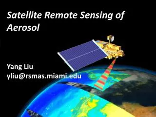
Aerosol remote sensing based on combined use of reflectance and polarization measurements. Itaru Sano and Sonoyo Mukai Kinki University Japan. Contents. 1. GCOM satellite series SGLI on GCOM-1C 2. Aerosol retrieval 2ch polarization method POLDER

E N D
Aerosol remote sensing based on combined use of reflectance and polarization measurements Itaru Sano and Sonoyo Mukai Kinki University Japan
Contents 1. GCOM satellite series SGLI on GCOM-1C 2. Aerosol retrieval 2ch polarization method POLDER 2ch polarization & 1ch total radiance method POLDER + GOSAT / CAI Application to biomass burning aerosols
Background & Objectiveof GCOM-1C / SGLI A goal of this work is to develop an efficient algorithm for global aerosol retrieval by using both polarization and total radiance data given by SGLI on GCOM-C. Japanese space agency (JAXA) has been developing the new Earth observing system, GCOM satellite series as contribution of GEO. GCOM-1 Climate will board the second generation global imager (SGLI) for monitoring the various kinds of Earth's reflectance's, atmosphere, land, and ocean). One of unique feature of SGLI compared to VIIRS or other imagers is polarization measurements at red and near infrared with high resolution (1 km x 1 km).
Global Change Observation Mission(GCOM) 2satelliteseriesfor5years,total13yearsobservation. • GCOM-W AMSR2 (AMSR-E follow onmicrowaveradiometer)forWATERCYCLE ( Satellite name : 雫 ) • GCOM-C SGLI (GLI follow on) forRADIATIONBUDGETand CARBONCYCLE GCOM-C(CLIMATE) AMSR2 GCOM-W (WATER) Shizuku SGLI Courtesy of Dr. Tanaka (JAXA/EORC) 5
SGLI on GCOM-1 Climate satellite SGLI ; Second Generation Global Imager + X flight direction +Y deepspace + Z earth SGLI IRS (Infrared Scanning Radiometer) SGLI VNR (Visible and Near IR Radiometer) Courtesy of Dr. Tanaka (JAXA/EORC) 6
SGLI : Second Generation Global Imager ←SWI-DET Non Polarized Observation Telescopes(24deg FOV x 3) SolarDiffuser EarthView Window Polarized ObservationTelescopes(55deg FOV x 2) Inside Sun Cal.Window TIR-DET→ About1.4m ←Optics About1.7m About 1.3m About0.6m Deep SpaceWindow Infrared Scanning Radiometer(SGLI-IRS) Visible and Near Infrared Radiometer(SGLI-VNR) ←Scan Mirror SGLI IRSBread Board Model 7 Courtesy of Dr. Tanaka (JAXA/EORC)
Visible and Near infrared radiometer SGLI-VNR 3 telescopes for total 70deg FOV • VNR non Polarized Obs. (NP) • 3 telescopes with 24deg FOV realize the total 70 deg FOV Observation (1,150km) • Wide wavelength range Observation • from 380 to 868 nm. • VNR Polarized Obs. (PL) • 2 telescopes with 55deg FOV each • for 673 and 868 nm Observation. • AT tilting mechanism for + / - 45deg • 55 deg FOV with 45 deg tilting corresponds to 1,150 km swath. NP Obs.Sub-Unit 673 & 868 nm telescopes ±45degtilting PL Obs.Sub-Unit AT : Along Track DirectionCT : Cross Track Direction 8 Courtesy of Dr. Tanaka (JAXA/EORC)
SGLI Specification • The SGLI features are 250m (VNR-NP & SW3) and 500m (TIR)spatial resolutionand polarization/along-track slant viewchannels (VNR-PL), which will improve land, coastal, and aerosol observations. 250m over the Land or coastal area, and 1km over offshore Multi-angle obs. for 674nm and 869nm 9 Courtesy of Dr. Tanaka (JAXA/EORC) option
VNR Polarization Observation • Intermediate scattering direction (60-120deg) should be observed for aerosol retrieval with +/- 45deg tilting radiometer(~ edge of POLDER's CCD). Tilt angle will be switched by command depending on this scattering angle requirement. • Backward Looking • Forward Looking • Nadir Looking (optional) or arbitrary angle (option) • 3 directional linear polarizer on each detector realize Stokes parameter observation(I, Q, U components) Required Scattering Angle 60 – 120deg BackwardLooking ForwardLooking ForwardLooking BackwardLooking satellite direction SOUTH NORTH satellite orbit direction 10 Courtesy of Dr. Tanaka (JAXA/EORC)
Polarized phase function : size information (rg= 0.05, 0.1, 0.2, 0.4 µm, cg=2.0 µm fix) m=1.45-0.0i fix 0.67 µm 0.87 µm Middle scattering region
Polarized phase function : refractive index (real part) (rg= 0.1 µm, cg=2.0 µm fixed) rfr=1.40, 1.45, 1.50, 1.55, rfi = 0.0 fixed 0.67 µm 0.87 µm Middle scattering region
Polarized phase function : refractive index (imag. part) (rg= 0.1 µm, rg=2.0 µm : fixed) rfr=1.45 fixed, rfi = 0.0, 0.0005, 0.001, 0.002, 0.004 0.67 µm 0.87 µm
SGLI polarization measurements (tilting operation) scat ang [deg] Backward (-45deg) Forward (+45deg) solar position (latitude) [deg] (-45 direction; backward) • SGLI measures the atmospheric light at the scattering angle from ~60 to ~120. Scat Ang Switch tilt angle to forward (+45 direction; forward) Scat Ang SGLI simulated scattering angle image Switch tilt angle to backward
Imprementation Plan: Milestone PFM BBM EM C2 Launch Phase-A Phase-B Phase-C Phase-D Project start GCOM-C1 launch System PDR System CDR Data Release Mission result evaluation Selection Ver.0 Ver.1 Ver.2 Ver.2.5 Ver.3 for C-1&2 Inplementation-1 Performance test Analysis using existing satellite data Imple. -2 Operation test Intensive Cal/Val phase Improvement with product version up Implement for C2 Version-ups & improvement 4. Post-launch development and improvement phase 1. Initial development 2.Performance development 3. Operational algorithm Development of algorithm performance and operational code FY 2028 FY 2015 FY 2019 FY 2023 GCOM-C1 GCOM-C2 GCOM-C3 Launch 5 years ~13 years 15 Courtesy of Dr. Murakami (JAXA/EORC)
Retrieval algorithms POLDER 2ch (red & NIR) radiance over ocean : AOT, and frac. of bi-md size 2ch (red & NIR) polarization over land : AOT, and frac. of bi-md size CAI + PARASOL 1ch (NUV) nadir radiance + 2ch (red & NIR) polarization over land : AOT, frac. of bi-md size, & aerosol type CAI 2ch (NUV, red ) nadir radiance + 2ch (red & NIR) polarization over vegetated area : AOT, frac. of bi-md size, & aerosol type SGLI (future algorithm) multi-channles radiance + 2ch (red & NIR) polarization over land : AOT, fraction of bi-md size, & complex ref idx.
Land surface and Sea-surface model Molecules Aerosols Altitude sea-surface land surface Soil Water Vegetation BPDF w/ IGBP & NDVI BPDF w/ Wind speed
Aerosols over Japan Aerosol optical thickness Angstrom exponent March 18, 1997 April 25, 1997
Validation rule with sun photo (AERONET) data Eleven sites of AERONET (Aire Adour, Banizoumbou, Bidi Bahn, Bondoukoui, Dakar, Dalanzadgad, GSFC, Los Fieros, Mfuwe, and Zambezi) are selected for validating the retrieved results from POLDER-1 data according to the following rules: 1) The AERONET measurements are selected within the +/- 30 minutes over flight ADEOS-1 satellite. 2) The values of AOT at wavelengths of 0.443, and 0.870 µm as ground based measurements are selected for calculating Angstrom exponent. 3) The AOT at wavelength 0.550 µm is estimated based on the Angstrom exponent and the measurement of 0.670 µm. 4) The POLDER results are selected within the ~20km (3x3 POLDER grid) square around the AERONET site.
Validation of retrieved results over land AOT (0.55 µm) Angstrom Cimel (AERONET) POLDER
Aerosol optical thickness Nov. 1996 Feb. 1997 Jun. 1997
PARASOL / POLDER April May June
GCOM-C / SGLI Polarization (0.67, 0.87 µm) with +/- 45 degrees along track tilting : 1000 m Visible and near infrared (11ch) : 250 m Shortwave infrared (4ch) : 250/1000 m Thermal infrared (2ch) : 250/500 m SGLI sensor mounted on GCOM-C satellite hasmulti-wavelength bands from UV to IR like ADEOS-2 / GLIand polarization data in NIR like POLDER. (JAXA)
Retrieval algorithms POLDER 2ch (red & NIR) radiance over ocean : AOT, and frac. of bi-mode 2ch (red & NIR) polarization over land : AOT, and frac. of bi-mode CAI + PARASOL 1ch (NUV) nadir radiance + 2ch (red & NIR) polarization over land : AOT, frac. of bi-mode, & aerosol type (m) CAI + PARASOL 2ch (NUV, red ) nadir radiance + 2ch (red & NIR) polarization over vegetated area : AOT, frac. of bi-mode, & aerosol type (m) SGLI (future algorithm) multi-channles radiance + 2ch (red & NIR) polarization over land : AOT, fraction of bi-mode, & complex ref idx.
Retrieval of biomass burning aerosols based on combined use of near-UV radiance by GOSAT/CAI & near-IR polarization by PARASOL/POLDER.
TANSO - CAI on GOSAT CAI – Cloud Aerosol Imager a complimentary sensor for Fourier Transform Spectrometer (FTS) launched on 23rd January, 2009. Four observing wavelengths : 380, 670, 870, 1600 nm. Level 1 data provide us with the TOA reflectance of the Earth.
Match up dataset of A-Train's PARASOL and GOSAT: time difference Apr. 25, 2009 ± 5 min ± 30 min
Estimation of ground reflectance 2nd minimum reflectance is chosen during a month at each pixel in order to reduce the cloud shadow effects. Furthermore, the cloud shadow effect on the neighbors is also considered in detail. Rayleigh atmospheric correction is adopted with DEM data. GOSAT / CAI (BGR: 380 , 870, 670nm) RGround :
Estimation of atmospheric light Satellite image 2nd min image Atmos. light image GOSAT / CAI (BGR: 380 , 870, 670nm)
Size distribution Bi-modal log-normal volume distribution Fine mode aerosols : r fine = 0.135 µm, fine = 0.43 µm Coarse mode r coarse=2.365 µm, coarse= 0.63 µm (Dubovik et al., JAS, 2002) Adjustment parameter (Fcoarse) : coarse mode fraction
Aerosol model bi-modal lognormal size distribution AERONET has been working since early 90's which provides enough knowledge of size distribution of aerosols. The above panels show the results of 6 categories by Omar et al. ; Mean radius of each mode and their sigma can be fixed. ; Volume of each mode varies with aerosol type and depends on AOT.
fine mode coarse mode Category Aerosol Type mode radius SD mode radius SD c 1 desert dust 0.12 1.48 2.83 1.91 c 2 biomass burning 0.14 1.56 3.73 2.14 c 3 background/rural 0.13 1.50 3.59 2.10 c 4 polluted continental 0.16 1.53 3. 55 2.07 c 5 polluted marine 0.17 1.61 3.27 2.00 c 6 dirty pollution 0.14 1.54 3.56 2.13 r r r Approximate Size Dist. Fn. available for all Fixed mode radius & variance Fine mode fraction “f” is a parameter for the size distribution
Aerosol model : carbonaceous aerosols Matrix f[%] :volume fraction of inclusions against matrix Inclusions Maxwell-Garnett (MG) mixing rule : internal mixture of aerosols ex) Matrix : m=1.46 - 0.0002i Inclusions: m=1.61 - 0.022i (Bohren and Wickramasinghe, Astrophys. Space Sci, 1977)
Refractive index (0.38 µm) from Maxwell-Garnett Single scattering albedo (0.38 µm) f : " SSA is decreasing according to the volume fraction of carbonaceous inclusions."
Vertical profile of biomass burning plume CALIPSO / CALIOP results show that the Biomass burning plume was concentrated under 3-5 km height. Aerosol vertical structure is considered based on the US std profile with plume concentration under 5 km. CALIOP 532nm Backscatter, on Aug. 8, 2010
Ground model ; BPDF Nadal and Bréon, 1999 Maignan et al. 2009
Retrieval process in practice A set of ta , a and is retrieved for each aerosol model based on POLDER Q U (670, 870) and GOSAT CAI I (380) R (380 nm) PR (870 nm) R (380 nm) PR (670 nm) R (670 nm)
Validation of retrieved results The AERONET AOT and Angstrom data are selected during the ± 30 min against the satellite overpass. Error bars : Min and max values of the measurements. a Ångström exponent
Summary SGLI on GCOM-1 C will take for aerosols, high resolution (1 km x 1 km ) polarimetric measurements at 2chs (0.67, 0.87 um) with simultaneous nadir total reflectance from 0.38 to 10 um. For carbonaceous aerosol retrieval, we propose simple algorithm based on combined use of near-UV radiance and polarized radiance at red and NIR bands. Future work for SGLI Dust aerosols: Spheroid DB (provided from Oleg) Efficient and fast algorithm for operational use including Oleg's inversion algorithms.