Download

1 / 64
640 likes | 765 Views
LIQUEFACTION, CRITICALITY AND COMPLEX SYSTEM. Jeen-Shang Lin Department of Civil and Environmental Engineering University of Pittsburgh 4/30/09 NTOU. Point Based Criteria. q c , (Mpa). f s , (kPa). stress. resistance. Depth (m). Motivation.

E N D
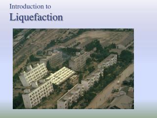
LIQUEFACTION, CRITICALITY AND COMPLEX SYSTEM Jeen-Shang Lin Department of Civil and Environmental Engineering University of Pittsburgh 4/30/09 NTOU
Point Based Criteria qc, (Mpa) fs, (kPa) stress resistance Depth (m) Kobe-Pitt Symposium on Disaster Risk Reduction and Response
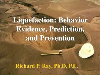
Motivation Identification of sites that are susceptible to liquefaction triggered by earthquakes is a crucial part of an earthquake hazard mitigation effort. Point failure criteria
Questions to be answered: • Is the soil susceptible to liquefaction? • If the soil is susceptible, will liquefaction be triggered? • If liquefaction is triggered, will damage occur? Answers to these questions require tackling some deep questions…..
Common large scale ground failures: Liquefaction Landslide Ground movement (uplift or subsidence) Debris flow Mud flow Kobe-Pitt Symposium on Disaster Risk Reduction and Response
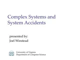
What is the deeper question? Reflections on Failure • Failures often have common fundamental physics and structures: Intrinsic nature, invariant scale measure. • It is important to view them from a unified framework. • Numerical analysis is difficult but not insurmountable. • We are very good at computation. But shouldn’t a computation be guided by a proper understanding of physics? Kobe-Pitt Symposium on Disaster Risk Reduction and Response
Intrinsic failure: Topology of a problem? Key block theory + discrete elements
Stresses induce fracture and block movements 47 removable out of 57 Simplified modeling of flow stress 53 removable out of 63
Three ways a soil may respond depending on their states (Intrinsic nature?) • Castro (1969) • liquefaction failure • dilative response • limited liquefaction failure Monotonic undrained triaxial tests on Banding Sands
Conventional computational approaches Constitutive modeling + FEM work quite well, but does not address a more fundamental question.
Mesh Based Partition of Unity: A new paradigm Problem domain Mathematical Mesh Physical Mesh
Same foundation with meshless methods: Partition of unity Diffusion element Element free Galerkin method Reproducing Kernel Particle Method h-p cloud method Partition of unity finite element method Extended finite element method Generalized finite element method
Covers, nodes and Elements Covers are nodes Overlapped covers are elements
The use of finite covers leads to node based computation Element Free Galerkin method Nodes lie inside a problem domain. Boundary, covers and supports (Belytschko et al. 1996.) Meshed Based Partition of Unity No restriction on nodes locations (XFEM)
Formulation Partition of Unity Function: Duarte and Oden (1996) Approximate Function Weak form of the discrete problem with penalty formulation
Mesh Based Partition of Unity: A new paradigm Failure computation has made substantial Pr Problem domain Mathematical Mesh Physical Mesh
Same foundation with meshless methods: Partition of unity Diffusion element Element free Galerkin method Reproducing Kernel Particle Method h-p cloud method Partition of unity finite element method Extended finite element method Generalized finite element method
Covers, nodes and Elements Covers are nodes Overlapped covers are elements
The use of finite covers leads to node based computation Element Free Galerkin method Nodes lie inside a problem domain. Boundary, covers and supports (Belytschko et al. 1996.) Meshed Based Partition of Unity No restriction on nodes locations (XFEM)
Formulation Partition of Unity Function: Duarte and Oden (1996) Approximate Function Weak form of the discrete problem with penalty formulation
Back to ScienceLiquefaction : What happened? Casagrande had envisioned that a “flow structure” would develop at liquefaction (Castro, 1969): “….during a liquefaction slide the relative position of the grains is constantly changing in a manner which contains a minimum resistance. He explained that the change from a normal structural arrangement of the grains to be flow structure would start almost accidentally in a nucleus and then spread through the mass by a chain reaction, and that such a reaction could explain the spontaneous character of liquefaction slide.”
Liquefaction as a Critical Behavior of a Complex System? A sand assembly is a complex system, and “critical state”, “phase transition”, “steady state” are also the focus points in the dynamics of various complex systems, including even biological systems (e.g., Kauffman, 1993). On the outset, a steady state in the terminology of nonlinear dynamics is often referred to as a “fixed point” or a “fixed point attractor” (e.g., Williams, 1997), as a system is attracted to a fixed state under sustained loading. The physics governing the process that leads to an attractor generally have something in common. It is believed here that linking liquefaction to the current understanding of nonlinear dynamics may also provide a better understanding for post-liquefaction behavior.
Self-Organized Criticality Castro and Poulos (1977) have proposed an interpretation for cyclic mobility. They postulated that large strains resulting from cyclic mobility in laboratory on dilative sands are due principally to redistribution of void ratio within the specimen during cyclic loading. In 1987, Bak, Tang and Wisenfeld proposed the concept of “self-organized criticality” (SOC). They discovered that large, dissipative complex system had the tendency of driving themselves into a critical state with wide range of length and time scale.
A percolation view? There can’t be no flow unless voids are connected into a path through a material domain. Kobe-Pitt Symposium on Disaster Risk Reduction and Response
Failure of a heterogeneous material A global failure requires local failure to be connected….
Failure of a heterogeneous material Failure is not static
Critical Threshold How wide spread needs the liquefaction be within a given site in order for it to fail? • We used percolation theory to address this issue: • A problem domain is first discretized with a regular lattice • Each lattice cell may be vacant or occupied with an occupancy rate, p. • We then asked, “What is occupancy level in a lattice at which it is possible to find a pathway through the unoccupied population of the lattice?” • The critical occupancy rate is called a percolation threshold, or critical threshold, pc. • One of our central issues is: “What portion of a site has to be liquefied before a site is considered liquefied?”
Renormalization Group Method Basic Failure group for Von Mises materials pc is found to be 0.618
Critical threshold pc is found to be 0.618
Verification of Percolation failure • We conduct strain control compression test simulation on Von Mises material using samples consists of 10,000 cells. • Two strength levels were selected; each cell was assigned one of the two strengths according to the random number generated. If the random number, which lay between 0 and 1, selected was less or equal to an assigned p, the lower strength was given; otherwise the higher strength was used.
Take a detailed look Cluster size distribution
Uniaxial experiment: bonded particles(initial void ratio=0.16) Red: location of failed bonds Deviatoric stress vs Axial strain
Failure ProgressionBreaking of bonds 0.066% axial strain 0.165% 0.198% 2.31%
same sample L=H(13203 particles) Deviatoric stress vs Axial strain
Failure ProgressionBreaking of bonds 0.198% axial strain 0.264%
Using an assembly of particles --Looking from a different angle usingan assembly of particles and conduct numerical experiment for understanding
A sample triaxial testinclude unloading reloading Devistoric stress vs axial strain WE are in the process of tracing the failure location and cluster size, as well as what happen at the largestrain. Volumetric strain vs axial strain
Concluding remarks • This is a work in progress. We are now using both particle codes and continuum code with bounding surface model with state variables to study the problem involving self –organization after failure. • We believe that looking into a scale invariance measure, the phase change from percolation view point can be invaluable.
Cell Traction Force Microscopy Method Jeen-Shang Lin In Collaboration with James H-C. Wang MechanoBiologyLaboratory Departments of OrthopaedicSurgery University of Pittsburgh
Migration Cell polyacrylamide gel Substrate Traction forces Cell traction force microscopy (CTFM) is recognized as a simple and effective method for quantifying cell traction forces.
B A B “Force-loaded” image “Null-force” image
Image Registration • Feature-based registration • Non-Feature Based Registration
Phase congruence • In the frequency domain, at locations of complex image intensity variation, the local Fourier components are maximally in phase. • local phase is also invariant to image brightness or contrast. • To determine the phase information spatially, one needs to process the images to simultaneously obtain the spatial and the frequency information. • Use filter bank: Gabor functions
Selected Features in null force image Matched featured in force loaded image