Download
1 / 16
160 likes | 283 Views
Sino-German Workshop on Electromagnetic Processing of Materials, 11.10 – 13.10.2004 Shanghai, PR China Magnetic Field Control of Heat and Mass Transport Processes in Industrial Growth of Silicon and III-V Semiconductors Crystals

E N D
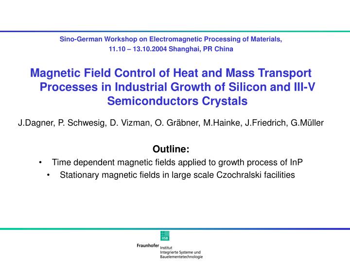
Sino-German Workshop on Electromagnetic Processing of Materials, 11.10 – 13.10.2004 Shanghai, PR China Magnetic Field Control of Heat and Mass Transport Processes in Industrial Growth of Silicon and III-V Semiconductors Crystals J.Dagner, P. Schwesig, D. Vizman, O. Gräbner,M.Hainke, J.Friedrich, G.Müller Outline: • Time dependent magnetic fields applied to growth process of InP • Stationary magnetic fields in large scale Czochralski facilities
Motivation Process: Vertical Gradient Freeze (VGF) growth of InP Task: Substrates with low dislocation density without additional dopands for lattice hardening Crucible Problem: Generation of dislocations during the relaxation of thermal stresses • Possible Solution: Usage of time dependent magnetic fields to control convective heat transfer • Change the shape of the solid liquid interface in order to minimize the von Mises Stress • Optimization using numerical modeling Melt Crystal
Numerical modeling • Furnace Setup : • Existing VGF setup located at the Crystal Growth Laboratory in Erlangen (currently used for R&D activities for S-doped InP) • Already optimized thermal field using numerical modeling • Numerical Modeling: • Global model of the complete setup for heat transfer with CrysVUn (conduction radiation and melt convection) • Quasistationary calculations for different position of the phase boundary • Investigated field types: • Rotating magnetic fields (RMF) • Traveling magnetic fields (TMF) Inert gas Boron-oxide Melt cover InP Crystal 9 Heating zones Insulation Crucible support Steel autoclave
Process time Applying RMF to the standard growth process Melt b<0 b>0 Crystal concave convex Interface Max. von Mises stress at solid liquid interface for different process times. Bending (b) of the solid liquid interface for different process times. No significant influence on the bending of the interface and the resulting von Mises stress
Standard Process Downward configuration Upward configuration Maximum velocity in the melt. 4,6 mm/s 5,3 mm/s 9,6 mm/s Only the down-ward configuration is useful Bending of the solid liquid interface 2,0 mm 1,6 mm 2,1 mm Max. von Mises stress at the phase boundary 1,2 MPa 0,6 MPa 2,1 MPa Applying TMF to the standard growth process – influence of the orientation of the Lorentz-force Streamlines Isotherms dT = 1k Aspect ration: 0.5
Applying TMF – Influence of the strength of the magnetic induction on the flow pattern Streamlines for different magnetic induction at a aspect ration of 0.9. Only half of the computational domain is show. • Function of the velocity in z direction has a minimum • The bending of the solid liquid interface changes from concave to concave-convex shape (hat or W-shape)
Applying TMF – Resulting von Mises stress at the solid liquid interface • Minimum of the von Mises stress at 5,5 mT, but the phase boundary has a W-shape. • Two contradicting optimization criteria: • Minimization of the bending of the phase boundary • Minimization of von Mises stress at the phase boundary
Conclusions –Part I • Rotating magnetic fields (RMF): • Only small influence on the bending of the phase boundary and the resulting von Mises stress(< 15%) • Higher growth velocities have no advantages, in contrast to prior studies on GaAs (Hainke et al. Magnethydrodynamics 39:513-519 2003) • Traveling magnetic fields (TMF): • Reduction of the resulting von Mises stress while maintaining a flat phase • boundary • Further reduction is possible if a W-shape interface does not create additional problems in the growth process • Major drawback for the practical application: The integration of an inductor for generating a TMF in a high pressure and high temperature vessel with corrosive atmosphere (Phosphor vapor) is complicated and expensive. • (Schwesig et al. Journal of Crystal Growth 226:224-228 2004)
Czochralski growth of Si crystals • Objectives for using magnetic fields: • Stabilization of convection • Reduction of temperature fluctuations • Control of oxygen transport and interface shape • Field strength: • several mT up to several hundreds of mT transversal axial cusp
Optimization of the seeding phase by reducing diameter fluctuations with without Magnetic field with Temperature without 5K Magnetic field 1mm with Diameter without Magnetic field Time in sec Hirmke, Study Work 2001
Czochralski growth of Si crystals under the influence of steady magnetic fields Determination of the temperature distribution in the melt and at the crucible wall by using a special thermocouple set-up Measured temperature distribution at the wall (lines) compared with calculated values (point). (in collaboration with Siltronic) Gräbner, Proc. EMRS 2000
Czochralski growth of Si crystals under the influence of steady magnetic fields wx = -20rpm, wc = 2rpm wx = -20rpm, wc = 5rpm Axial Field 128mT wx = -20rpm, wc = 5rpm 2D - Simulation Experiment Cusp Field 40mT wx = -20rpm, wc = 5rpm 2D - Simulation Experiment Temperature distribution in a Si melt with 20kg under different process conditions – stationary numerical simulations with fixed shape of the melt pool; low Reynolds number k- model (CFD-ACE); magnetic fields by FZHDM1. [1] Mühlbauer et. al. J.o.Cryst.Growth 1999 pp 107
Czochralski growth of Si crystals under the influence of steady magnetic fields 300mm Crystal rotation: wx = -15rpm Crucible rotation: wc = 4rpm 3D view Side view Shape of solid/liquid interface under the influence of a horizontal magnetic field. Calculations (magnetic and flow field) with STHAMAS 3D. Free melt surface. The temperature is color-coded. Vizman, PAMIR 2002
Conclusions –Part II • Static magnetic fields: • Widely used for large scale Czochralski process • Measurement techniques for obtaining temperature values in the melt are available • Comparing this measured data to values obtained by numerical simulations show a qualitative agreement • Simulation of Czochralski process is still a matter of intense research
Acknowledgement This work is financially supported by the German federal ministry of education and research and Humbolt foundation. The calculations with CFD-ACE were performed at SILTRONIC, Burghausen, Germany