Download
1 / 33
330 likes | 428 Views
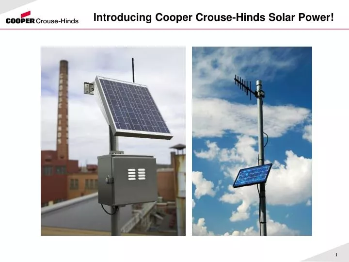
Introducing Cooper Crouse-Hinds Solar Power!. Solar Power. Background What is it, how does it work Component functions, ratings, certifications Information needed to select Competition Product info, pricing, lead-times, tech support . Background.

E N D
Solar Power • Background • What is it, how does it work • Component functions, ratings, certifications • Information needed to select • Competition • Product info, pricing, lead-times, tech support
Background • Why are photovoltaic (solar power) panel assemblies needed? • cost effective alternative • to provide power where or when line power is not available • Other methods, eg generator, fuel cell, wind not practical • Why is CCH offering? • wireless I/O, also applications for lighting, instruments, sensors • Why not just offer batteries? • What is the difference between solar for ordinary locations and for Division 2 hazardous locations? • Key questions to select: • what location to install? (ie how much sun?) • what load, in amperes? (size the panel and the battery) • how often will the load need power?
Terminology • Off grid: solar power with battery backup • Grid tie: tied into utility power • Stand-alone: large (KW) solar power assembly • Hybrid: standalone coupled with generator • Inverter: electronic equipment to convert DC voltage from solar to AC for load
Benefits of solar power modules • Eliminate need for power infrastructure, and the time and costs to install • Enables monitoring/control in remote applications • Modules are easy to install, minimal maintenance required • Pre-wired per the NEC/CEC minimize installation time and wiring errors • Quality components maximize reliability and system life • Systems can be designed for higher load and voltage requirements (other than wireless)
Applications • Installed with remotely located devices and equipment • Examples: • Obstruction lighting in remote locations • Instrumentation • Cathodic protection • Navigational aids • Seismic monitoring • Video surveillance • Irrigation monitoring and control • Telecommunications • Tank and well level monitors • Flow meters
Benefits to customers • Enhance Safety and Productivity • Supply power to monitor remote assets and their locations to improve emergency response time and eliminate time-consuming, on-site inspection • Solar is a mature technology used in applications requiring safe/reliable power sources • Reduce Operation and Labor Costs • Eliminate infrastructure needed to develop line power in remote applications • Pre-wired kits allow for quick installation by any qualified electrician • Maintenance-free battery life eliminates battery replacement for 4+ years • Reliable Performance in Any Environment • Recommended temperature range: -30ºC to 50ºC (consult factory for more extreme temperatures) • Class I, Division 2 assemblies available
Solar Module Review • Thin Film • Mono or Single Crystalline • Poly or Multi Crystalline
Solar Module Review • Thin Film Modules • Larger area for the same electrical output (2X) • Lower efficiency about 7% • Does well in low light levels and off angle radiation • Does not perform well in high temperatures • Lighter weight, no tempered glass • 6% market share
Solar Module Review • Mono Crystalline Modules • Smaller footprint • High efficiency about 18% • Most expensive to manufacture • 37% market share
Solar Module Review • Poly or Multi Crystalline Modules • Smaller footprint than thin film • High efficiency about 16% • Not as expensive to manufacture as Mono • 57% market share
PV Module (Solar Panel) • Photovoltaic Module • Made of high efficiency polycrystalline silicon modules, capable of weathering any environment. • High efficiency, small footprint – more compact than other solar technologies • Fully encapsulated panel resists harsh weather conditions (hazardous environments, hail, rain, 90mph wind) • Integral junction box with terminal connection block with pre-installed UV rated cable, providing ease of installation • 25 year expected life • Installation angles are important for performance and maintenance Solar Panel • FM Certified: - Class I, Division 2, Groups A, B, C, D Higher efficiency, smaller profile, longer life than other comparable solar tech panels (e.g. thin film)
Mounting Structures • Roof & Ground Mount • Rapid Rac
Mounting Structures • Top of Pole • Single module • Multi module
Mounting Structures Side of Pole • Single module • Multi module
Regulator (aka controller) • Efficient and reliable solid state components • Maintains health of the battery, prevents severe discharging • Rated for 25% overloads • Encapsulated electronics with marine rated terminals for superior corrosion resistance • Temperature compensation provides reliable power supply at extreme temperatures • Green charging / red low voltage disconnect (LVD) indicators-- help expedite troubleshooting Regulator • UL Listed: - UL 1604 • FM Certified: - Class I, Division 2, Groups A, B, C, D - CSA 22.2 No. 213-M1987 Regulators channel the sun’s energy to the equipment when needed, or charge the battery when energy is not required
Battery Technologies There are three (3) general types of battery technologies that are used in photovoltaic (PV) off-grid application Flooded AGM Gelled
Battery Technologies Flooded
Battery Technologies Flooded Most common in Home Power applications Large size offering Requires controlled environment Non sealed system Requires quarterly inspections to determine electrolyte level and specific gravity Less initial cost
Battery Technologies AGM Absorbed Glass Mat Sealed system- All gases are recombined and returned to battery system Electrolyte is suspended in a glass mat Large range of product sizes, many manufacturers Confused often with a gel-cell Lower cost and shorter cycling life than gelled electrolyte
Battery Technologies Gelled Electrolyte
Battery Technologies Gelled electrolyte • Designed for maintenance-free deep cycling solar applications • Sealed, valve-regulated, gelled electrolyte • Low stand loss minimizes deterioration between transport and storage • Non-spillable ICAO, IATA, and DOT ratings ensure safe transport without the need for special containers • Handles heat better than AGM or Flooded • Higher initial cost, heavier weight Battery • UL Listed: UL1989 Specifically designed batteries supply power to the load when sunlight decreases or at night
Battery Technologies Does depth of discharge affect cycle life? Yes! The harder any battery has to work, the sooner it will fail. The shallower the average discharge, the longer the life. This is why it’s important to size a battery system to deliver at least twice the average power required, to assure shallow discharges. Typical Battery Cycling Ability vs. Depth of Discharge Typical Life Cycles Capacity Withdrawn Gel AGM 100% 450 150 80% 600 200 50% 1000 370 25% 2100 925 10% 5700 3100
Circuit Protection • Compact DIN rail mounted design • Isolates and protects all components and terminals, factory wired • Canadian certifications in process • FM approved circuit protectors are available for use in Class I, Division 2 hazardous applications. • Circuit Protectors • • UL Listed: • - UL 489 • UL 1077 • • FM Certified: • Class I, Division 2,Groups A, B, C, D • Units < 10A: T6 • Units > 10A: T4A Ensures the protection of all components. Provides convenient, quick disconnect for user.
Enclosure • Corrosion resistant, aluminum enclosures house all electrical components (battery / regulator / wiring), improve system reliability, and minimize maintenance • Prewired for ease of installation, terminals clearly marked • Different mounting options possible (poles, walls, or other structures) • Trunk latches provided for NEMA 3R seal • Customer may determine where to locate cable entries Enclosure • UL Listed: - UL 508A, NEMA 3R (standard); NEMA 4 and 4X options available Protects solar kit components and wiring from the elements, allows for safe air exchange for the battery, prewired control
Sizing Solar Arrays (4) Questions that your customer will be able to provide the answer to: 1 - What is the power consumption expressed as either watts or amps 2 - Duty-cycle…How long is the equipment running, continuous, intermittent, etc. 3 - What is the equipment voltage, generally but not always this is: 12VDC / 24VDC / 48VDC 4 - Where is the geographic location for the system, different locations have different solar resource values
Selecting a System • STEP ONE • Determine the equivalent sun hours of the application you would like to install a solar kit into. • Example: • Atlanta, GA 4.0 Equivalent Sun Hours • In case you are wondering, • Syracuse, NY …1.5 (ESH)
Selecting a System STEP TWO Determine the load requirements for your application in Amp-hours / day. For wireless applications, determine the power of your device in amps (for CCH wireless radio power consumption, refer to the calculator on our website: http://www.crouse-hinds.com/wirelessIO/Calculator/Files/CCHSolarCalc.xls STEP THREE Determine the duty cycle (i.e. 100% for continuous vs. 50% for 12 hours per day) of your load. STEP FOUR Adjust for a 1.2 service factor to account for load requirement variability STEP FIVE Select the solar kit capable of meeting or exceeding the load requirements (in Amp-hours / day) for your application. Note: Assemblies for higher load requirements are available. Load requirement (Amp-hours / day) = (amps of device x duty cycle x 1.2) x 24 hours / day
Selecting a System Example: 200 mA device, continuous duty cycle, Atlanta GA Load requirement = (200 mA x 100% x 1.2) x 24 hours / day = 5,760 mA-hr / day Load requirement = 5.8 Amp-hours / day used in a region which has 4 equivalent sun hours
Pricing, lead-times, etc • Pricing: loaded for all cataloged items, other load reqts by request • Lead-time: 2-3 weeks ARO (US) • Tech support: Adam Dix, Joe Geswaldo, Dave Holloway
Summary • CCH Solar Panel Assemblies provide: • Remote source power for wireless and other uses • Performance and long life from reliable, field proven components • Ease of installation from modular design, and prewired components • Low TCO due to proven components with low maintenance requirements • A logical solution to sell along with CCH Wireless I/O applications in remote areas • Assemblies for higher load requirements, or grid-tie, consult factory